Disassembly and Assembly: Solenoid Valves
Issue 2
127
Part No. 306-0430-102
Solenoid Valves
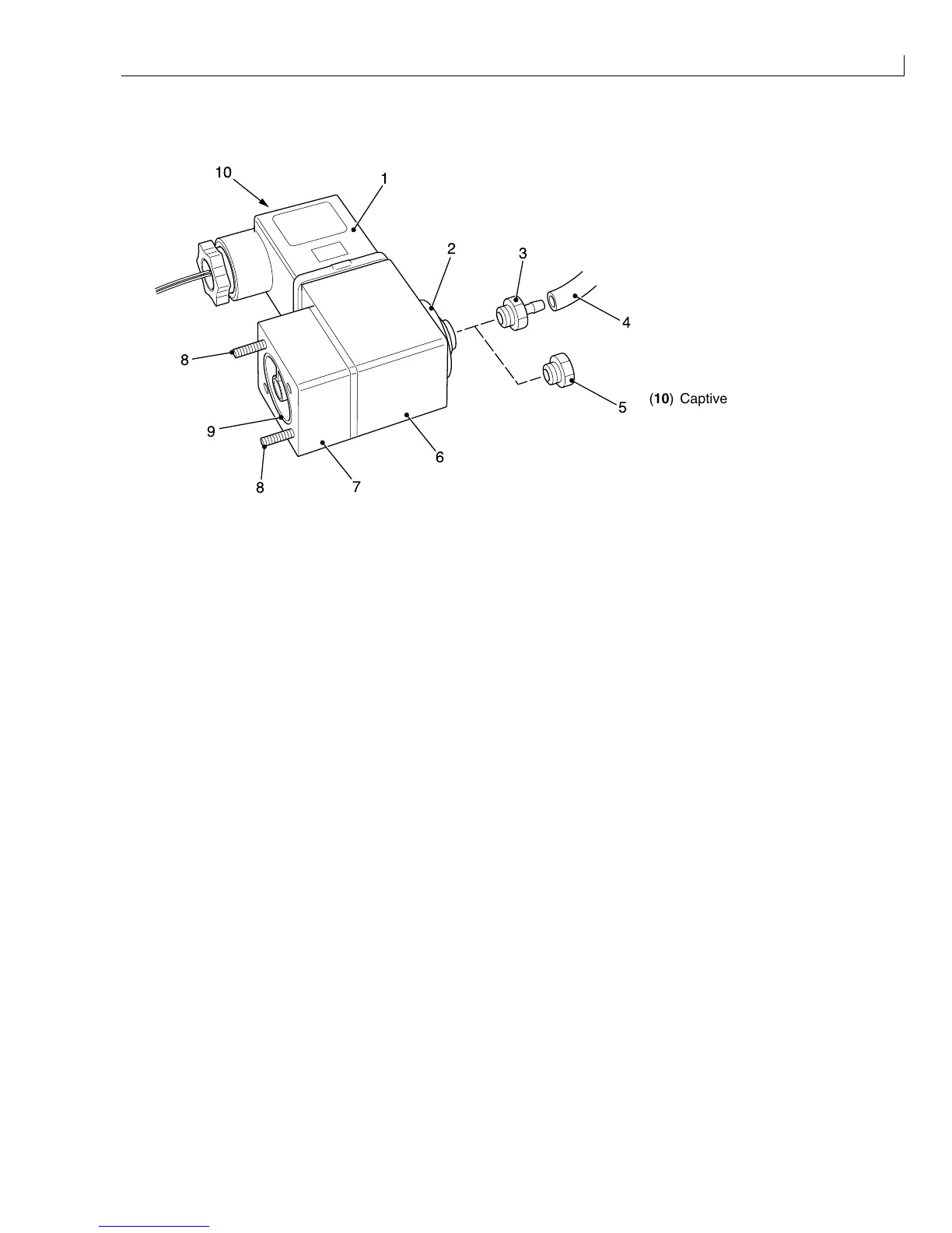
(
1
) Electrical connector
(
2
) Circlip
(
3
)Barb
(
4
) Tube
(
5
)Plug
(
6
) Solenoid windings
(
7
) Valve block
(
8
) Retaining screws
(
9
) Dual O-ring seal assembly
2
3
4
5
6
7
8
1
10
9
8
(
10
) Captive retaining screw
Figure 62 Solenoid Valve Components
Removal
1
Remove the electrical connector (Figure 62 (
1
)) from the body of the valve after slackening the captive
retaining screw (
10
).
2
Remove the tube (
4
) from the barb (
3
) on valves V3, V8 or V6 (note the colour of the stripe on the tube).
3
Remove the plug (
5
) from valves V1, V2, V4 and V10.
4
Remove the circlip (
2
) and slide the solenoid windings (
6
) off the valve block (
7
) (note the orientation of the
solenoid).
5
Remove and retain the two screws (
8
) securing the valve block to the manifold.
6
Remove the valve block, complete with O-ring assembly. Retain the O-ring assembly (
9
).
Installation
1
Fit the O-ring assembly (
9
), retained at
Removal
step
6
, to the valve block (
7
).
2
Fit the valve block to the manifold and secure it with the two screws (
8
) retained at
Removal
step
5
.
3
Slide the solenoid windings (
6
) on to the valve block and secure with the circlip.
4
Refit the electrical connector (
1
) and secure it with the captive screw.
5
Refit the tube (
4
) on to the barb (
3
) on valves V3, V8 or V6 (ensure the tube with the correct colour stripe is
fitted).
6
Refit the plug (
5
) on to the valves V1, V2, V4 or V10.