Disassembly and Assembly: Phase Detector
Issue 2
133
Part No. 306-0430-102
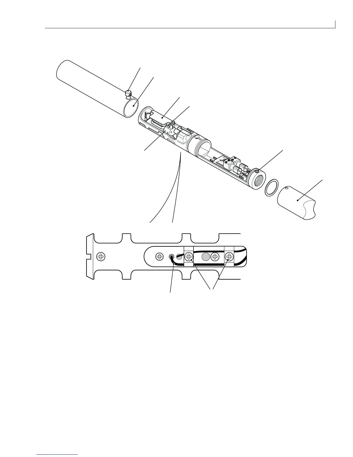
Phase Detector
1
3
2
9
7
8
6
4
5
(
1
) Printhead front cover (
6
) Rear cover
(
2
) Top deflector plate (
7
) Phase detector cable
(
3
) Phase detector (
8
) Phase detector clamping screw
(
4
) Knurled screw (
9
) Cable clamp screw (x2)
(
5
) Rear cover securing screw
Figure 66 Phase Detector Removal and Installation
Removal
1
Slacken the knurled screw Figure 66 (
4
) and slide the front cover off the printhead.
2
Remove and retain the two rear cover securing screws (
5
) and slide the rear cover (
6
) back until it is clear of
the printhead.