Disassembly and Assembly: Head Manifold
Issue 2
131
Part No. 306-0430-102
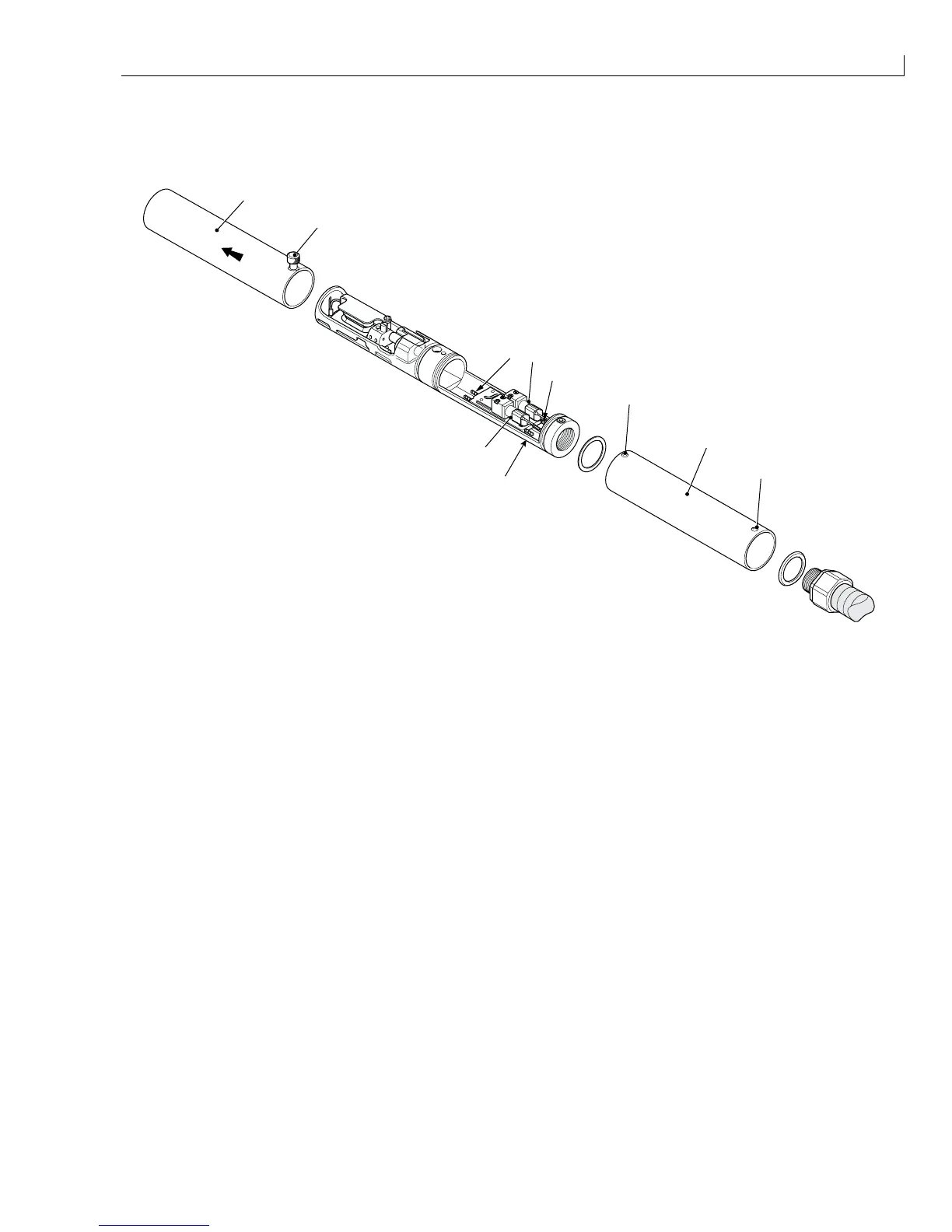
Head Manifold
The head manifold incorporates the gutter detect module and the head heater.
1
2
3
3
4
2
5
8
7
6
(
1
) Knurled screw (
4
) Electrical connections (
7
) Feed Valve
(
2
) Rear cover securing screws (
5
) Rear cover (
8
) Return valve
(
3
) Ink barb (
6
) Front cover
Figure 65 Head Manifold
Removal
1
Slacken the knurled screw (Figure 65 (
1
)) and slide the front cover (
6
) off the printhead.
2
Remove and retain the two rear cover securing screws (
2
).
3
Slide the rear cover (
5
) back over the umbilical until it is clear of the printhead.
4
Remove the heatshrink from the five electrical connections (
4
) at the rear of the head heater. Make a note of
how the wires are connected and then unsolder the connections.
5
Disconnect the electrical connections to the feed valve (
7
) and return valve (
8
).
6
Remove the ink barbs (
3
) from the front and rear of the head manifold.
7
The head heater can now be removed from the printhead.