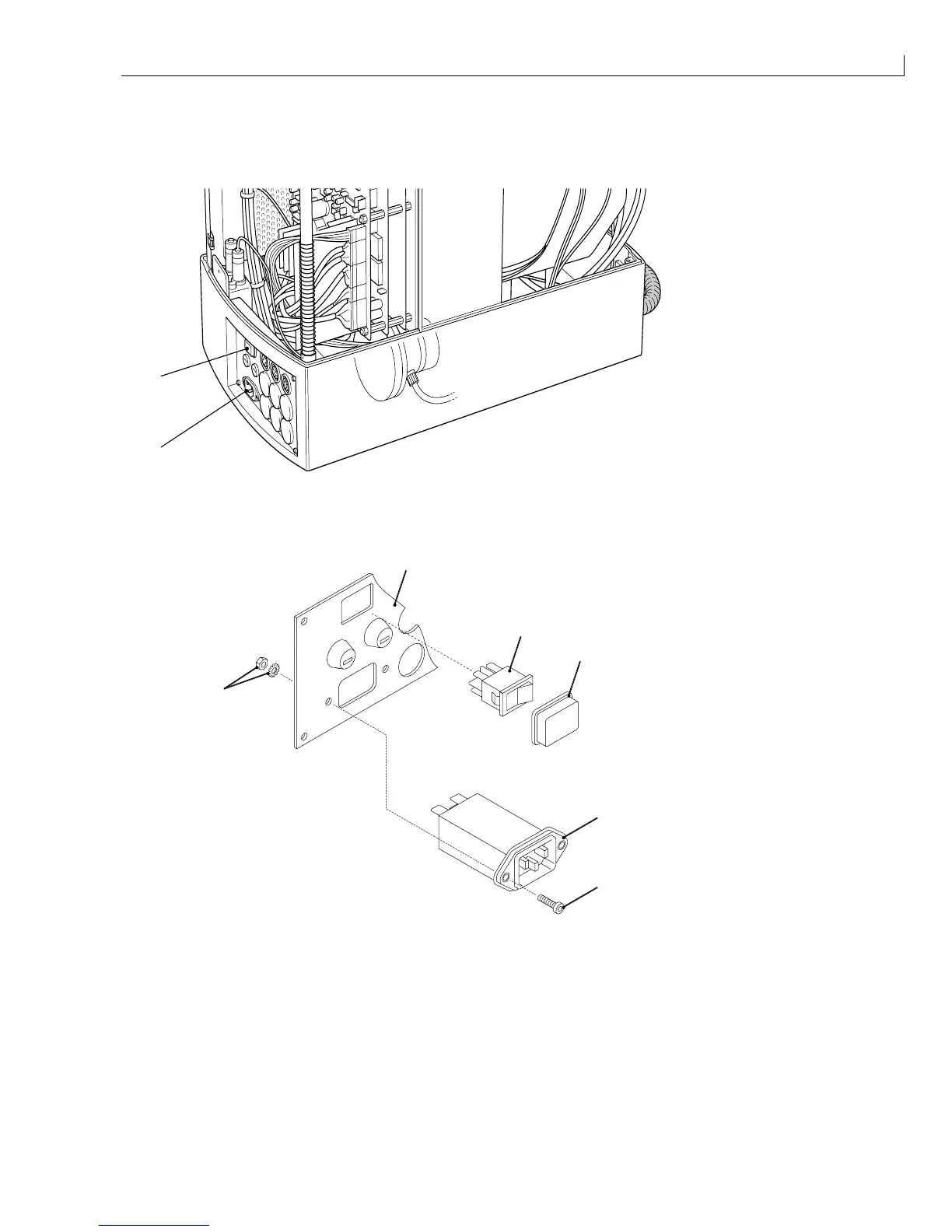
(
1
) Mains inlet connector
(
2
) Mains switch
Figure 56 Mains Inlet Connector and Mains Switch – Location
1
2
3
4
5
6
(
1
) Connector panel
(
2
) Mains switch
(
3
) Switch cover
(
4
) Mains inlet connector
(
5
) Securing screw
(
6
) Nut and washer
Figure 57 Mains Inlet Connector and Mains Switch - Removal and Installation
Removal
1
Remove and retain the two screws (Figure 57 (
5
)), nuts and washers (
6
) that secure the inlet connector (
4
)
to the connector panel (
1
).
2
Withdraw the inlet connector from the printer and disconnect the cables from the terminals at the rear. Note
the orientation of the cables for installation.