System Calibration and Test: I/O Board LED Check
Issue 2
27
Part No. 306-0430-102
I/O Board LED Check
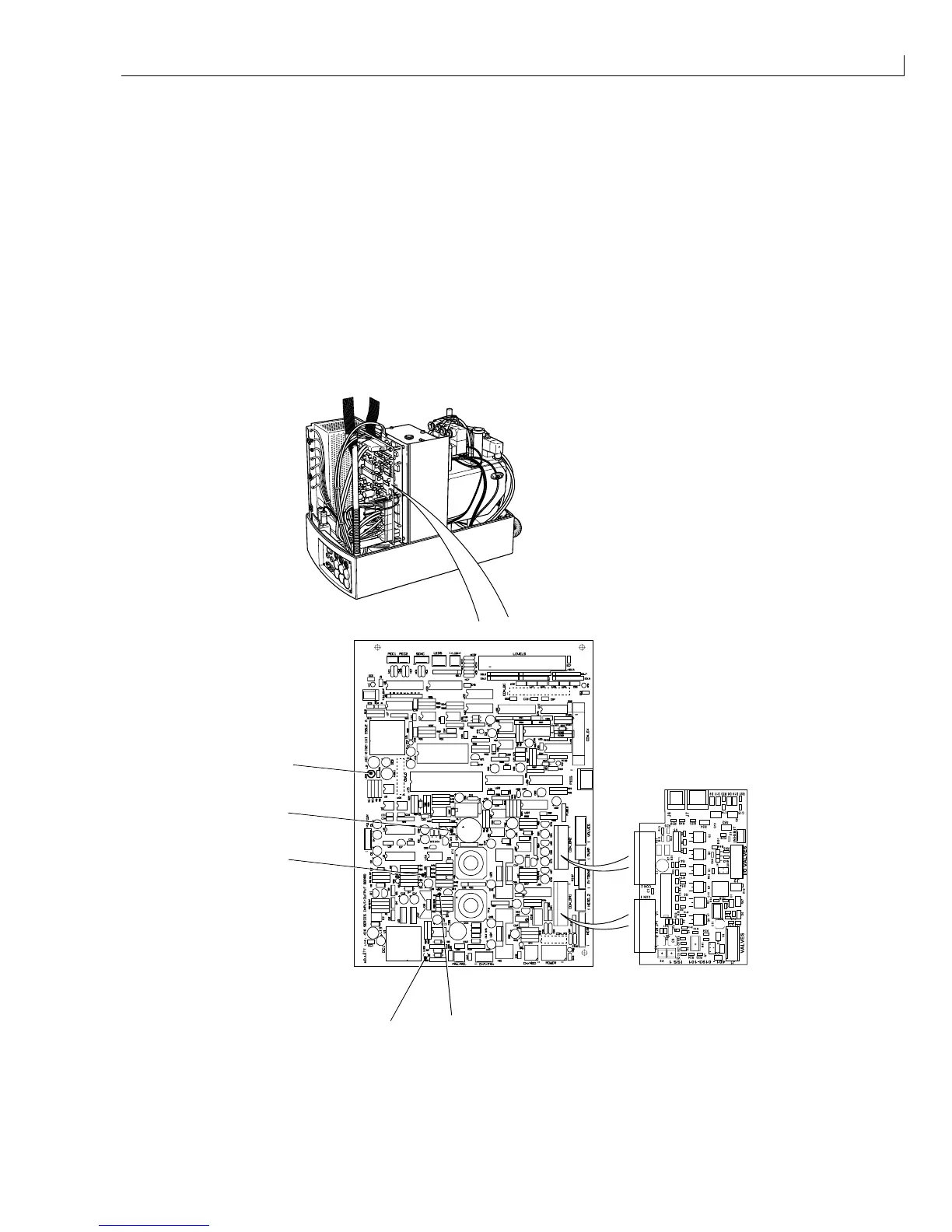
1
Remove the cabinet side covers. Check that LEDs 1, 3, 4 and 5 on the I/O board are illuminated and that
LED2 is dimly illuminated. The LEDs represent the following voltage rails:
LED1 (green) +12 V customer's isolated supply for shaft encoder/photocell.
LED2 (clear lens that glows
red when illuminated)
285 V
(+15 V = dim with printhead cover off, +285 V = bright with printhead cover on).
LED3 (yellow) -24 V supply.
LED4 (red) -15 V supply.
LED5 (green) +24 V valve/pump/heater supply.
2
Refit the cabinet side covers when the checks are complete.
1
3
2
4
5
(
1
) LED 4 (red); -15 V (
3
) LED 2 (red); +285 V (
5
) LED 1 (green); +10 V
(
2
) LED 3 (yellow); -24 V (
4
) LED 5 (green); +24 V
Figure 13 I/O Board Status LED Location