Installation: Product Sensors
Issue 2
13
Part No. 306-0430-102
Product Sensors
Figure 6 shows a photocell (
8
) connected via a cable (
5
) to PRINT TRIGGER 1 on the connector panel.
The printer can be configured to use two product sensors (PRINT TRIGGER 1 and PRINT TRIGGER 2).
Note: The PRINT TRIGGER 2 option requires the use of non-standard system software.
1
The photocells may be either NPN or PNP devices. Set Jumper JB1 (Figure 7 (
3
)) on the I/O board to match
the device type. Table 1 lists the settings for jumper JB1.
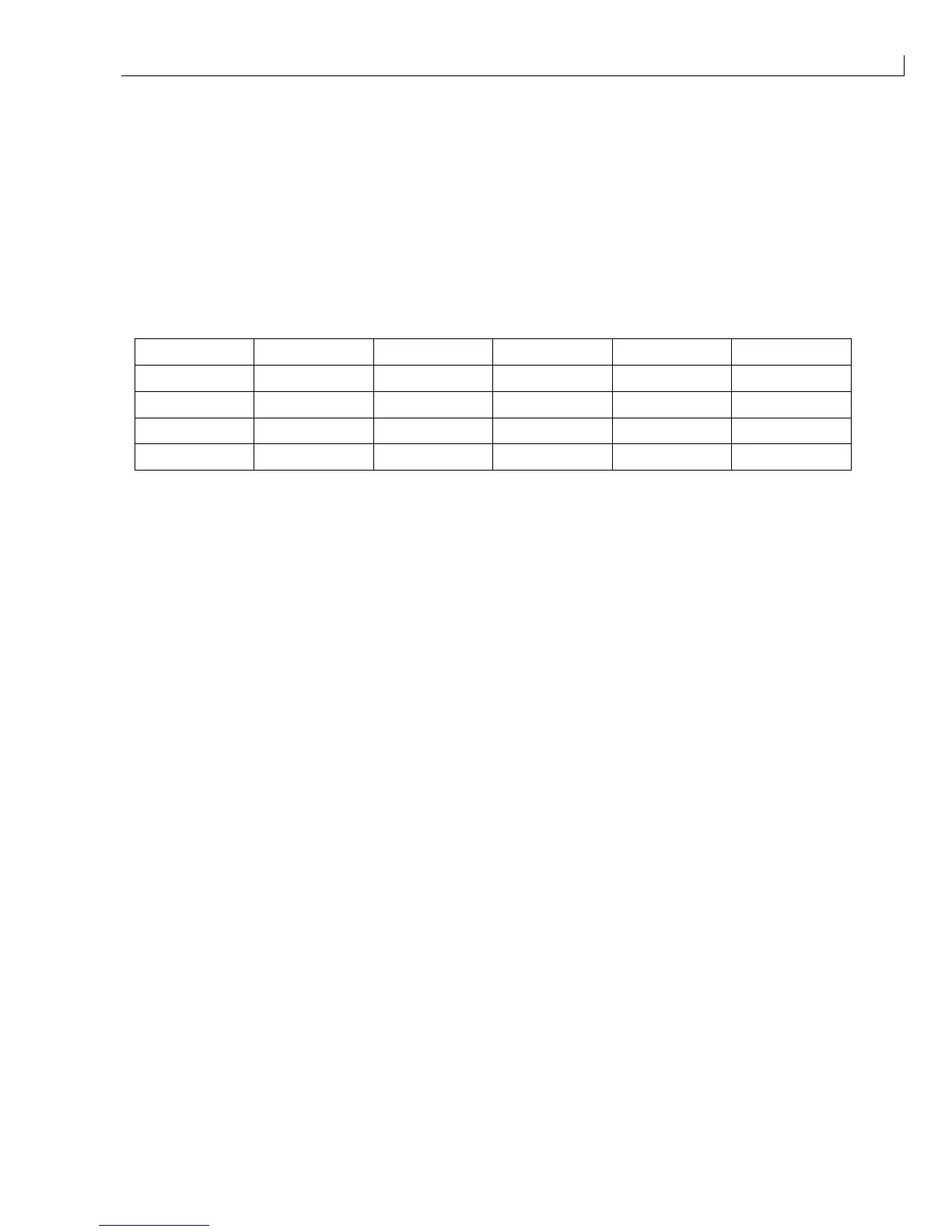
Table 1 Jumper JB1 Settings
Print trigger Device type Jumper 1 Pins Jumper 2 Pins
1 NPN A 1-2 C 3-4
1 PNP B 2-3 D 4-5
2 NPN F 6-7 H 8-9
2 PNP G 7-8 I 9-10
2
Connect the printer to the mains supply and set the on/off switch to
I
(on).
3
Select the
Photocell Setup
option from the
Configure
menu.
4
Set the relevant
Photocell level
(s) to
Active high
or
Active low
dependant upon the device type.
(NPN = Active high: PNP = Active low).