System Calibration and Test: Ink Viscosity Measurement
Issue 2
41
Part No. 306-0430-102
Ink Viscosity Measurement
Note: Before testing viscosity, ensure that the printer is at normal operating temperature.
1
Set up the syringe viscometer over a beaker that contains a thermometer.
2
Using the large syringe supplied, draw out at least 60 ml of ink from the mixer reservoir.
3
Cover the viscometer syringe nozzle, using a gloved finger, and fill until the ink is level with the top of the
syringe.
4
Using a stopwatch, time the flow of ink through the viscometer from the time when the finger is removed
until the last drop of ink falls from the nozzle.
5
Make a note of the time, and also the temperature indicated on the thermometer.
6
Apply the temperature compensation factor (given on the graph supplied with the viscometer) to the time
recorded and trace a reading on the main Time versus Viscosity graph (supplied with the viscometer).
Caution – Incorrect Measurement
If the temperature compensation factor is not used, the end result could be incorrect
by as much as 40%.
7
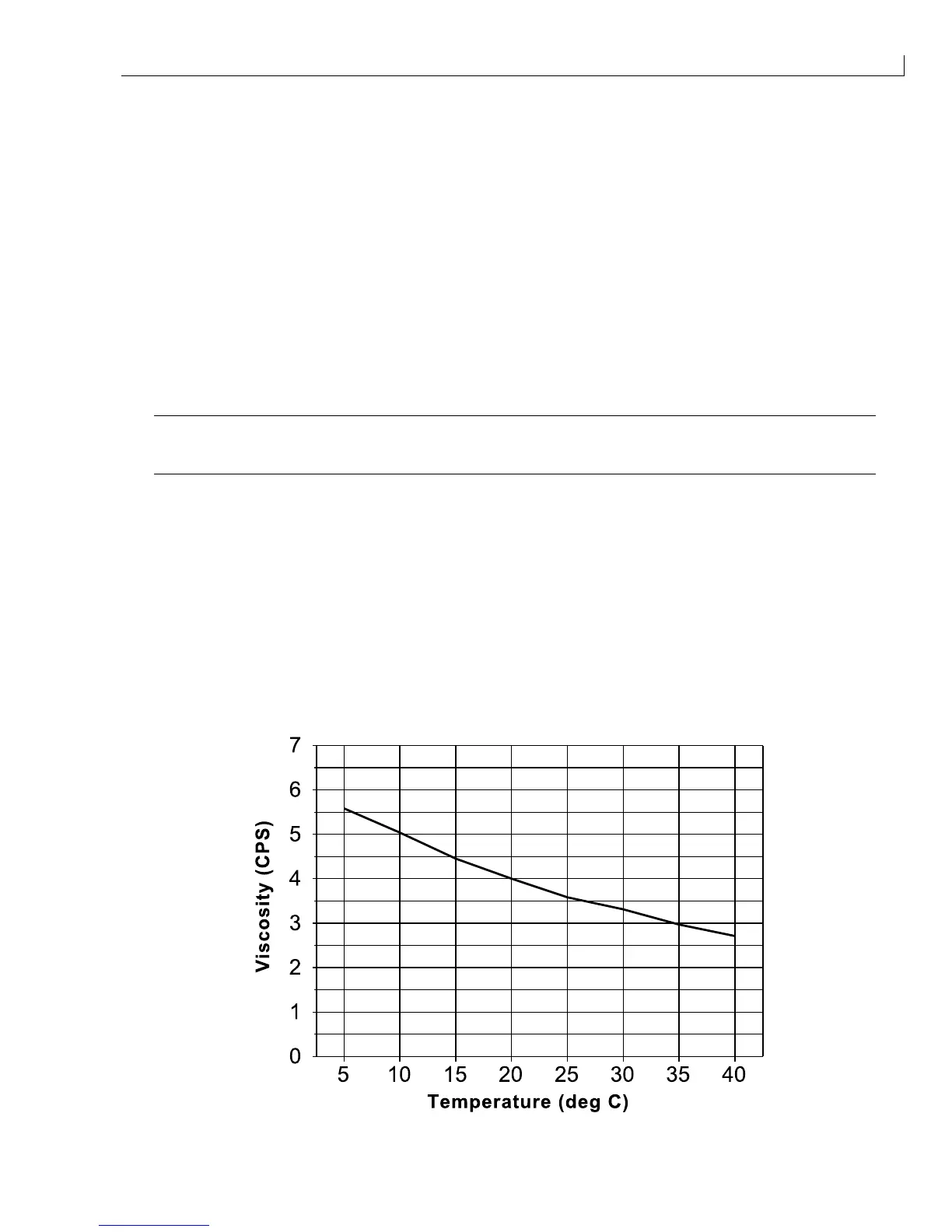
Refer to the temperature versus viscosity graph that relates to the ink being used. The graphs are listed in
the next section.
8
Relate the temperature noted at step
5
to the horizontal axis of the graph. Use the graph to calculate the
optimum viscosity (vertical axis) for the ink.
9
Compare the measured viscosity to the optimum viscosity to determine whether the viscosity is high or low.
Temperature/Viscosity Graphs
This section contains graphs of temperature versus viscosity for the range of inks used in the 400 Series
printers.
CIJ MK 390ID Black