430 Ink Jet Printer Service and Maintenance Manual
46
Issue 2
Part No. 306-0430-102
Table 36 PSU Board General Specification
Table 37 PSU Board Output Specifications
Main Assemblies
The printer comprises four main assemblies:
•
Cabinet.
•
Printhead.
•
Electronics system.
•
Ink system.
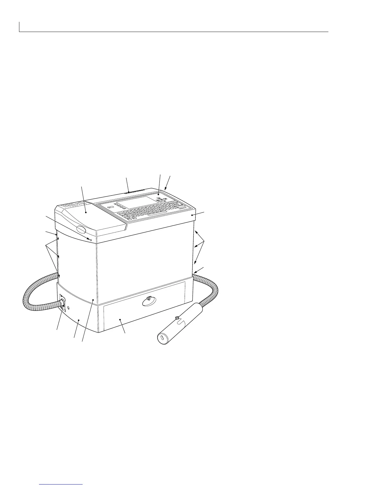
Cabinet
(
1
) Reservoir filler cover
(
2
) Vent
(
3
) Control panel
(
4
) Top cover fastener
(
5
) Top cover
(
6
) Side cover fasteners
(
7
) Connector panel
(
8
) Filter cover
(
9
) Side cover
(
10
) Base
1
2
4
5
6
7
9
6
3
8
9
10
11
4
(
11
) Umbilical outlet
Figure 17 Printer Cabinet
Top Cover
The top cover (
5
) is moulded from a plastic material and houses the following:
The control panel (
3
).
A hinged reservoir filler cover (
1
) that gives access to the ink and top up reservoir fillers.
A vent (
2
) that allows heat and vapour to escape from the enclosure.
The top cover is secured in position by two fasteners (
4
) which are screwed in to release the cover. When raised,
the top cover is supported on two telescopic struts, which gives access to the internal components of the printer.