Disassembly and Assembly: Umbilical
Issue 2
141
Part No. 306-0430-102
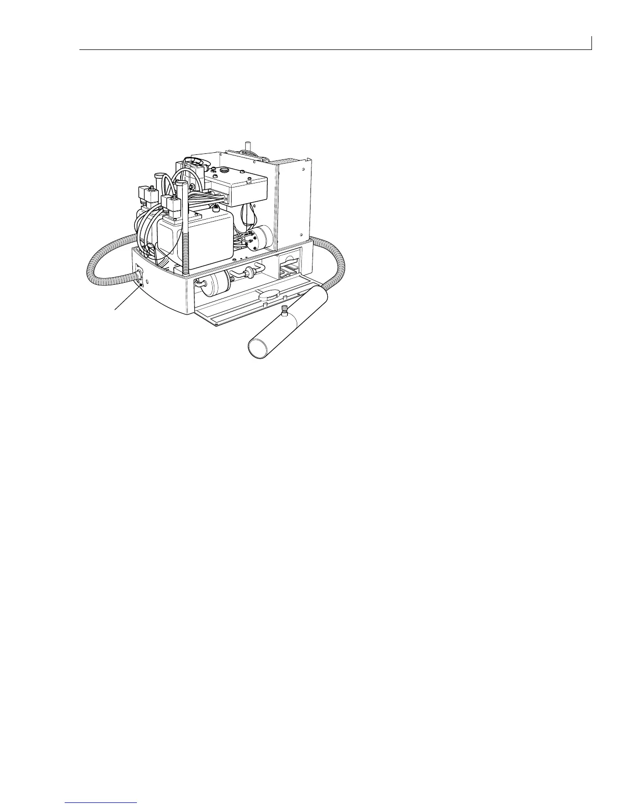
Umbilical
The umbilical gland is attached to the printer by four retaining screws.
1
(
1
) Umbilical gland
Figure 70 Umbilical Gland
Notes for Figure 71 Umbilical Connection Details
A
Fit earth wire supplied with umbilical assembly. Loop the earth wire through the ferrite ring (item
52
)
six times.
6
Secure the earth wire using 2-off tie wraps (item
31
).
B
1
Strip back outer sheath 130 mm, separate the screen and cut to 90 mm.
2
Cover the screen with 75 mm heatshrink (item
63
).
3
Cover the join using 30 mm of item 58.
4
Crimp the screen and 225 mm length of item
57
with item
49
.
C
1
Strip back the outer sheath to 35 mm.
2
Separate the screen and signal wire.
3
Sleeve the screen with yellow heatshrink (item
47
).
4
Cover the join with 30 mm min. black heatshrink (item
29
).
5
Terminate all wires with a crimp terminal (item
56
).
D
1
Strip back the outer and screen to 10 mm.
2
Bare the inner wire back 3 mm and tin with solder. Cover the end of screen with 40 mm heatshrink
item
29
.
E
1
Strip back the outer sheath and screen to 20 mm.
2
Cover the join with 30 mm black heatshrink (item
29
).
F
1
Strip back the outer sheath and screen 40 mm
2
Cover the join with 30 mm black heatshrink (item
29
).