Installation: Commissioning
Issue 2
5
Part No. 306-0430-102
(
1
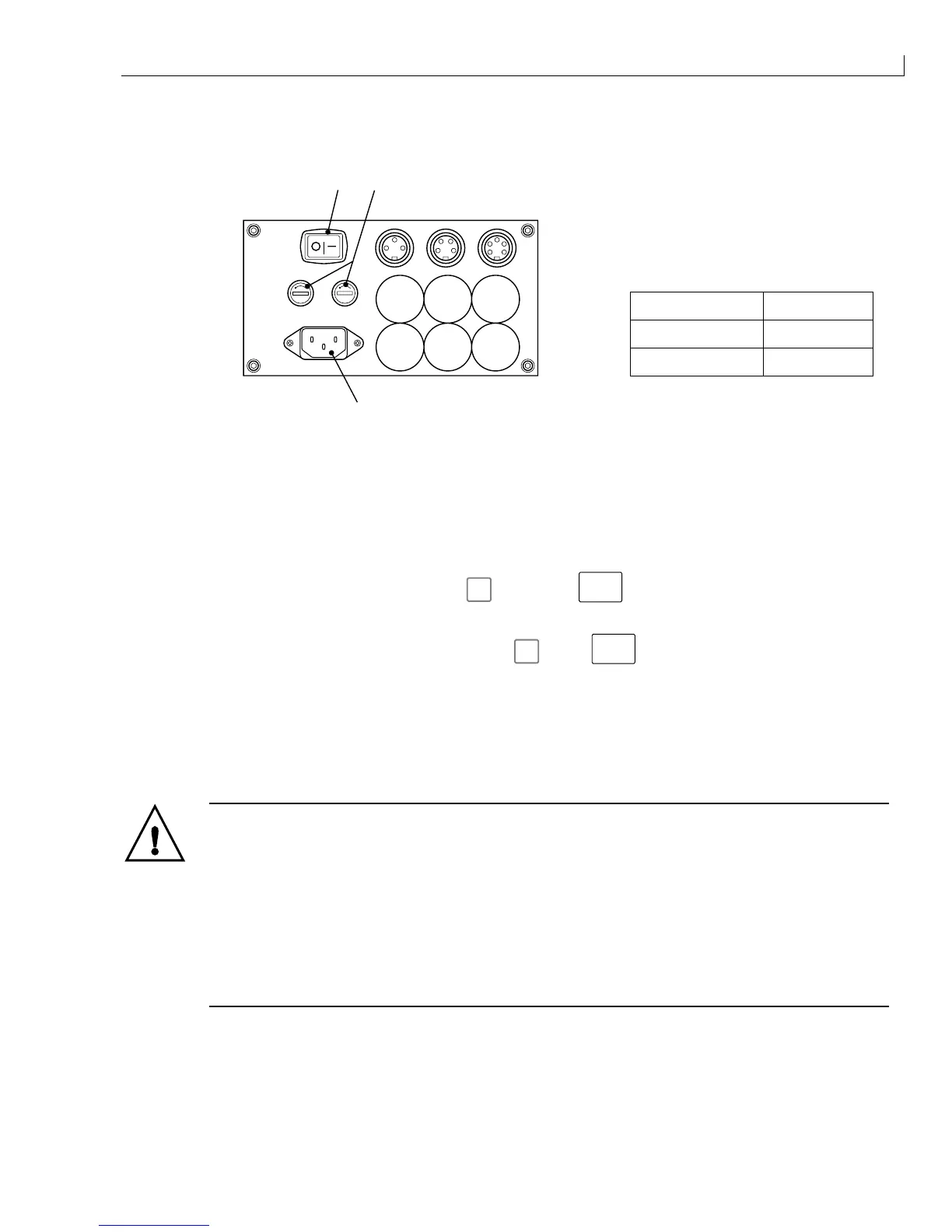
) On/Off switch
(
2
) Supply fuse holder
(
3
) Mains inlet socket
Mains Voltage Fuse Rating
110 V AC 5 A
230 V AC 3.15 A
3
21
PRINT TRIGGER 1 SHAFT ENCODER COMM 1
Figure 4 Connector Panel and Fuse Ratings
4
Connect the mains electrical supply to the mains inlet socket (
3
) and set the On/Off switch (
1
) to
I
(On). The
printer PSU will automatically detect and adjust to the mains voltage.
The printer remains uninitialised and the quick screen is displayed on the LCD panel.
5
If
nothing is visible on the LCD display, press
f3
, then press
ctrl
and
L
. Press any key to set the
contrast when the LCD is visible.
6
If the menu system cannot be accessed by pressing
f3
, press
ctrl
and
Z
, then
P
, enter the MASTER
password and repeat step
6
.
7
Access the
Password
menu and enter the MASTER password.
8
Remove the filler plug (Figure 3 (
1
)) and prime the mixer bowl (
2
) with approximately 250 ml of the correct
ink using a syringe and a length of 40 mm x 6 mm tube. The Ink Out icon will cease to be displayed when
approximately 250 ml is added to the mixer bowl.
WARNING - HANDLING INK, SOLVENT AND TOP-UP
The ink, solvent and top-up are irritating to the eyes and respiratory system. To prevent
personal injury when handling these substances:
Always wear protective clothing and rubber gloves.
Always wear goggles with side-shields or a face mask. It is also advisable to wear safety
glasses when carrying out maintenance.
Apply barrier hand cream before handling ink.
If ink or top-up contaminates the skin, wash immediately with soapy water. DO NOT use
washdown or solvent to clean ink stains from the skin.
9
Ensure that the complete 250 ml is added before proceeding.
10
Refit the filler plug (
1
) to the top of the FMS.
11
Refit the side covers, ensure that the orientation is correct as noted, secure the side cover fasteners
(Figure 3 (
4
)).