Technical Description: Control Electronics
Issue 2
65
Part No. 306-0430-102
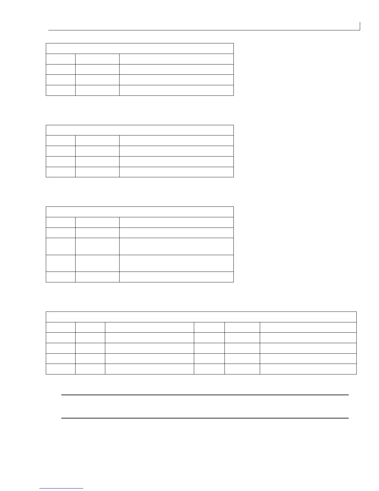
PEC1 (
1
) - Product sensor 1 via the connector panel
Pin No. Signal Function
1 +V0 Positive DC supply to sensor
2 EXT PEC 1/2 Input from sensor
3 0 V Common
Table 11 I/O Connector PEC1
PEC2 (
2
) - Product sensor 2 via the connector panel.
Pin No. Signal Function
1 +V0 Positive DC supply to sensor
2 EXT PEC 1/2 Input from sensor
3 0 V Common
Table 12 I/O Connector PEC2
SENC (
3
) - Shaft encoder via the connector panel.
Pin No. Signal Function
1 +V0 Positive DC supply to shaft encoder
2SHAFT
ENCODER A
Input A from shaft encoder
3SHAFT
ENCODER B
Input B from shaft encoder
4 0 V Common
Table 13 I/O Connector SENC
LEDS (
4
) - LEDs are fitted on the front panel to mimic traffic lights.
Pin No. Signal Function Pin No. Signal Function
1 Red + Red LED anode (+) 5 Red - Red LED cathode (-)
2 Yellow + Yellow LED anode (+) 6 Yellow - Yellow LED cathode (-)
3 Green + Green LED anode (+) 7 Green - Green LED cathode (-)
4 Strobe + Strobe LED anode (+) 8 Strobe - Strobe LED cathode (-)
Table 14 I/O Connector LEDS
Caution - Equipment Damage
The I/O Board LEDS connector must not be used to drive anything other than LEDs as specified
otherwise damage may occur.