ENGINE
M6060, M7060, WSM
1-S48
(Continued)
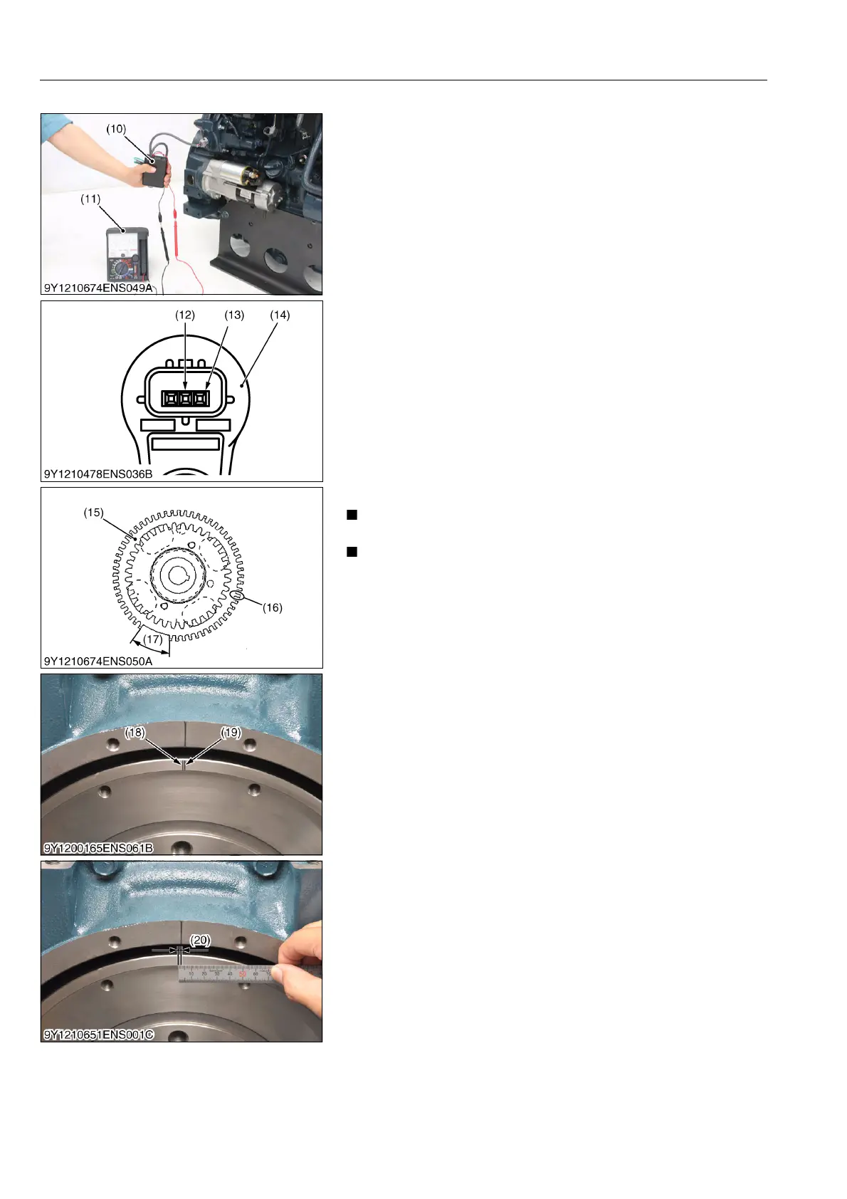
9. Connect a connector of the rotation sensor signal interface unit
(10) (see page G-62) to the crankshaft position sensor (14).
10. Connect each clip of the rotation sensor signal interface unit
(10) to the same test lead color of the tester (11).
11. Switch on the rotation sensor signal interface unit (10).
12. Turn the flywheel and make sure that the voltage of the
crankshaft position sensor goes from 0 → 5 V or 5 → 0 V.
13. Rotate the flywheel and align the crankshaft position sensor to
the part of the pulsar gear (15) that is missing teeth (17).
14. The 14th tooth (16) from the missing teeth is the standard.
15. Slowly turn the flywheel counterclockwise and stop the flywheel
at the point where the needle of the tester changes momentarily
from 0 → 5 V, the 14th tooth.
16. That point is where the crankshaft position sensor detects TDC.
17. Set the tri-square (6) on the reference line (9) on the flywheel
housing side and mark the detection point of crankshaft position
sensor TDC (19) on the flywheel.
18. Measure the interval (20) between the crankshaft TDC (18) and
the detection point of crankshaft position sensor TDC (19).
19. Calculation of fuel injection timing correction 1.0 mm (0.039 in.):
0.321 °.
Corrected angle = 0.321 ° × actual interval
20. Overwrite the injection timing correction value in the ECU.
• Using analog tester is easier to see the voltage change.
• When the crankshaft position sensor detects the teeth of
the pulsar gear, the tester indicates 0 V.
• The position where the needle of the tester changes
momentarily from 0 → 5 V is the detection point of
crankshaft position sensor TDC (19).
• The reference line indicates the crankshaft TDC (18) of the
crankshaft. If the detected TDC is ahead of the crankshaft
TDC, it is considered minus. If the detected TDC lags
behind the crankshaft TDC, it is considered plus.
9Y1210828ENS0067US0
(10) Rotation Sensor Signal Interface
Unit
(11) Tester
(12) Ground Terminal
(13) Output Terminal
(14) Crankshaft Position Sensor
(15) Pulsar Gear
(16) 14th Tooth
(17) Missing Teeth
(18) Crankshaft TDC
(19) Detection Point of Crankshaft
Position Sensor TDC
(20) Interval