HYDRAULIC SYSTEM
M6060, M7060, WSM
7-S23
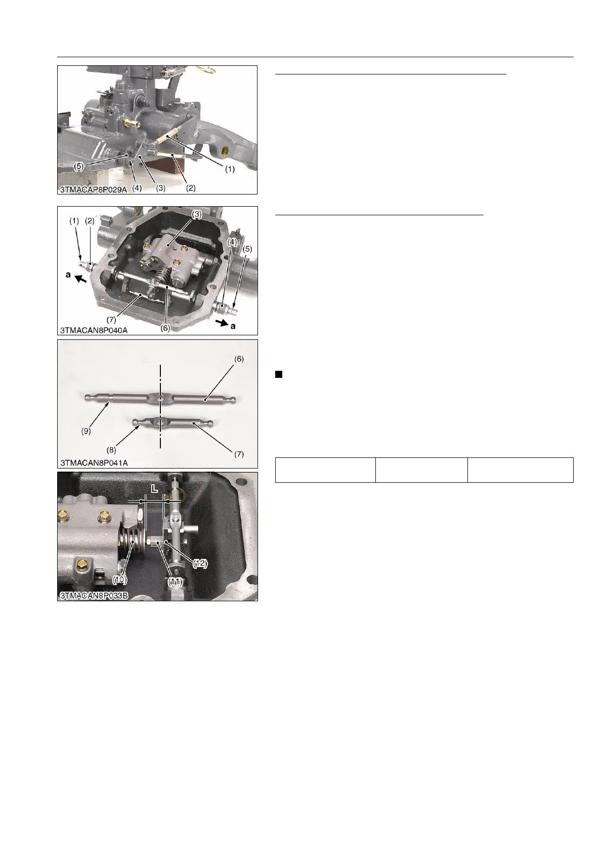
Position Feedback Rod and Draft Feedback Rod
1. Tap out the roll pin (4), remove the position feedback rod (1)
with position feedback lever (3).
2. Remove the draft feedback rod (2) with draft feedback lever (5).
(When reassembling)
• To adjust the position feedback rod (1) and the draft feedback
rod (2), see page 7-S10 and 7-S12.
9Y1210828HYS0025US0
Draft Spool Lever and Position Spool Lever
1. Push out the draft feedback shaft (2) and position feedback
shaft (1).
2. Push out the draft shaft (4) and position shaft (5).
3. Remove the draft spool lever (6).
4. Remove the control valve (3) then remove the position spool
lever (7).
(When reassembling)
• Fix the with groove side (9) on the draft spool lever (6) and
shorter side (8) on the position spool lever (7) face to the
hydraulic operating lever side.
• Be sure to fix the O-rings to the control valve and apply grease
to them.
• Do not disassemble the spool joint 1 (11) from the spool
(10) unless necessary.
If disassembled due to unavoidable reasons, record the
installation length (L) between the spool join 3 (12) and
spring retainer (as shown in the figure).
When reassembling, be sure to make to a former length.
9Y1210828HYS0040US0
(1) Position Feedback Rod
(2) Draft Feedback Rod
(3) Position Feedback Lever
(4) Roll Pin
(5) Draft Feedback Lever
Length (L) Factory specification
24.5 to 25.0 mm
0.965 to 0.984 in.
(1) Position Feedback Shaft
(2) Draft Feedback Shaft
(3) Control Valve
(4) Draft Shaft
(5) Position Shaft
(6) Draft Spool Lever
(7) Position Spool Lever
(8) Shorter Side
(9) Groove
(10) Spool
(11) Spool joint 1
(12) Spool joint 3
(a): Push Out Direction