Page 102 160337-000 Rev D, 30 September, 2013 Xiotech—Proprietary
ISE User Guide Monitoring
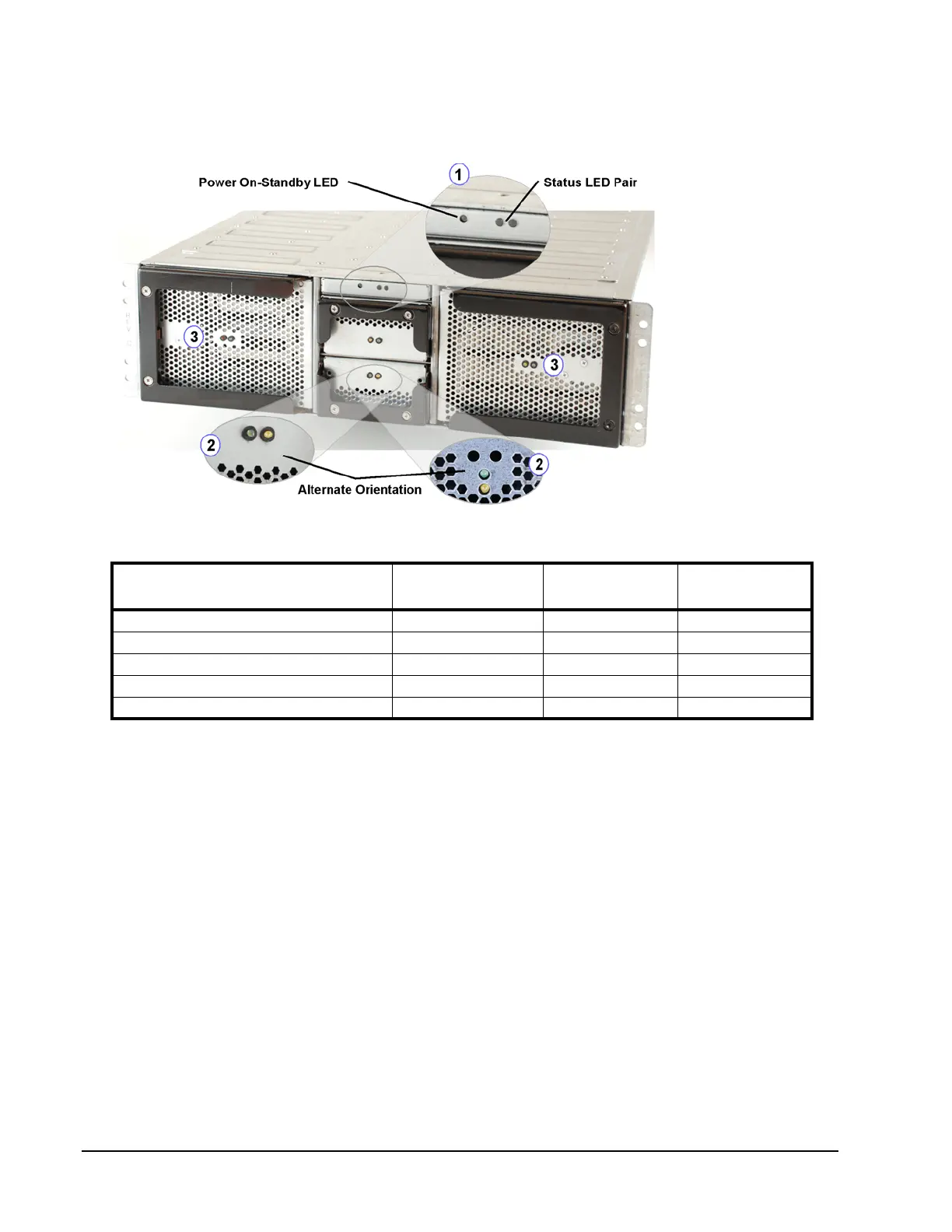
With the bezel removed the exposed LEDs indicate the overall state of the ISE with the three clustered LEDs
(blow-up 1 below) that are located on the System Status Module. The System Status module is the small
horizontal panel in the center of the chassis above the supercapacitor units (see Figure 73). The definitions for
the various states of these LEDs are listed in Table 24.
Figure 73. System Status Module—LEDs
Table 24: System Status LED States
The state of the individual ISE FRUs is indicated by pairs of LEDs on each FRU. Each DataPac,
supercapacitor or battery unit, and power supply has one green and one amber LED. The green and amber
LED pairs on each MRC (shown in Figure 76 on page 105) operate as follows.
In the figure above, the blow-ups labeled 2 show the LEDs that indicate the state of the supercaps. The state of
the DataPacs is indicated by the LED pairs labeled number 3.
Back LEDs
The ISE backside LEDs are intended for use in conjunction with the ISE management interfaces. The LEDs
give an indication of the state of the power supplies and the MRCs.
1. LED pair nearest the Ethernet ports (
1
), just above the I/O Extender input, shows the state of the MRCs.
2. LED pair nearest the set of Small Form-Factor Pluggable (SFP) Fibre Channel connectors (
2
) indicates as
follows:
• Lit green LED indicates host connection is present
• Un-lit amber LED indicates normal operation
3. LED pair located on the power supplies (
3
) shows the state of the power supplies.
Condition
Power On/Standby
Dual-color LED
Green LED in
Status LED Pair
Amber LED in
Status LED Pair
No power applied OFF OFF OFF
Standby (see “Power On State” on page 37) AMBER OFF OFF
Normal operation GREEN ON OFF
ISE locate GREEN Flashing Flashing
One or more component in failed state GREEN OFF ON
 Loading...