380
Duty cycle of PWM output =n /65535×100%
PWM use the unit of 0.1Hz, so when set S2 frequency, the set value is 10 times of the
actual frequency (10f). E.g.: to set the frequency as 72 KHz, and then set value in S2 is
720000.
When X0 is ON, output PWM wave; When X0 is OFF, stop output. PMW output doesn’t
have pulse accumulation.
Note: it needs to connect 1K ohm amplification resistor between output terminal and common
terminal when using PWM instruction.
Example
There is a LED drived by DC24V. It needs to control the brightness of the LED. In order to
decrease the power loss of wave collector, turn ON the switch at the moment it is OFF, then
turn it OFF. This process will cycle. Connet a transistor between the power supply and LED.
The pulse signal will input from the transistor base terminal. The current between base and
emitter is pulse. The LED input voltage is proportional to the duty ratio. The LED input
voltage will be changed by changing the duty ratio. There are many methods to change the
value. The normal way is pulse width modulation (PWM) which means only changing the ON
holding time but not changing the ON frequency.
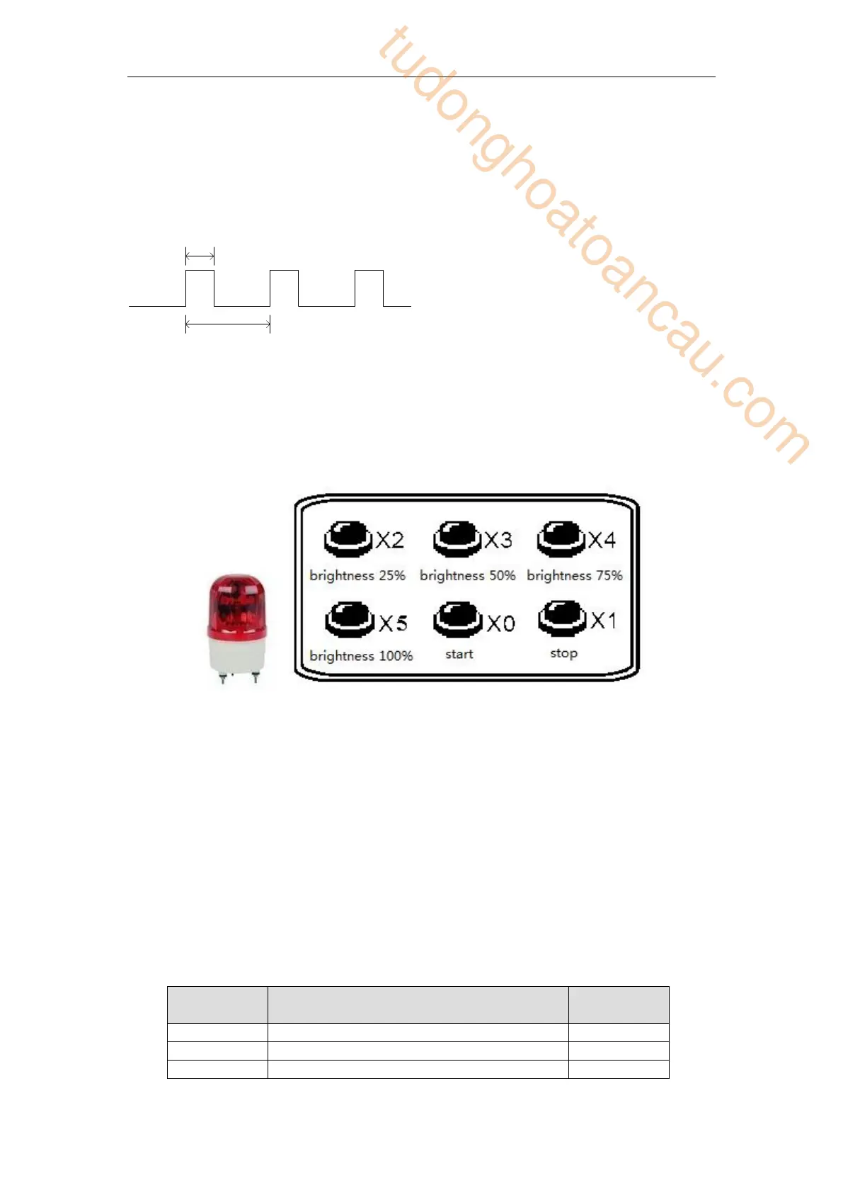
This example applies the PWM technology to the LED brightness adjustment. The controller
can accpet 24V PWM control signal. The brightness range includes 25%, 50%, 75%, 100%.
The brightness is controlled by the PWM duty ratio.
Element explanation:
Start button, X0 is ON when pressed.
Stop button, X1 is ON when pressed.
25% brightness button, X2 is ON when
In the left graph:
T0=1/f
t/T0=n/65535
tudonghoatoancau.com
 Loading...