5-12
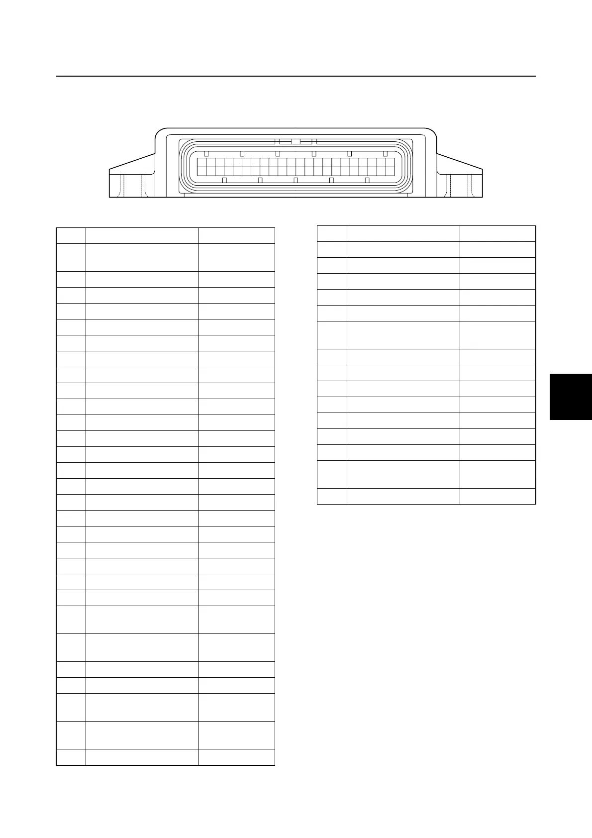
ECM coupler layout
0
1
2
3
4
5
6
7
8
9
10
A
ECM coupler layout
1 2 3 4 5 6 7 8 9 10111213141516171819202122
23242526272829303132333435363738394041424344
No. Connecting part Color
1
6Y8 Multifunction
Meter
White
2 Remote control Green
3 Remote control Pink
4 Remote control White
5 Water detection switch Blue/White
6
7 Air temperature sensor Black/Yellow
8 Sensor ground Black
9 Shift cut switch Blue/Yellow
10 Sensor power source Orange
11 Water pressure sensor Blue/White
12 Speed sensor Blue
13 Engine start switch Yellow
14 Pulser coil #1 White/Red
15 Pulser coil #2 White/Black
16 Main relay Yellow/Green
17 Fuel injector #4 Purple/Green
18 ISC Green/Black
19 ISC Green
20 ISC Green/Red
21 ISC Green/Yellow
22 Ignition coil #1, 4 Black/Orange
23
6Y8 Multifunction
Meter
Blue
24
Alert indicator (low oil
pressure)
Pink/White
25
26 YDIS White/Black
27
Diagnostic flash indi-
cator
Blue/White
28
Alert indicator
(overheat)
Pink/Black
29 Oil pressure sensor Pink/White
30 Battery power source Red/Yellow
31 Neutral switch Blue/Green
32 Ground Black
33 Air pressure sensor Pink/Green
34 TPS Pink
35
Engine temperature
sensor
Black/Yellow
36 Trim sensor Pink
37 Thermoswitch Pink
38
39 Fuel injector #2 Purple/Black
40 Fuel injector #1 Purple/Red
41 Fuel injector #3 Purple/Yellow
42 Ground Black
43
High-pressure fuel
pump
Blue
44 Ignition coil #2, 3 Black/White
No. Connecting part Color
Circuit diagram / ECM coupler layout
 Loading...


