5-30
Ignition units and components
0
1
2
3
4
5
6
7
8
9
10
A
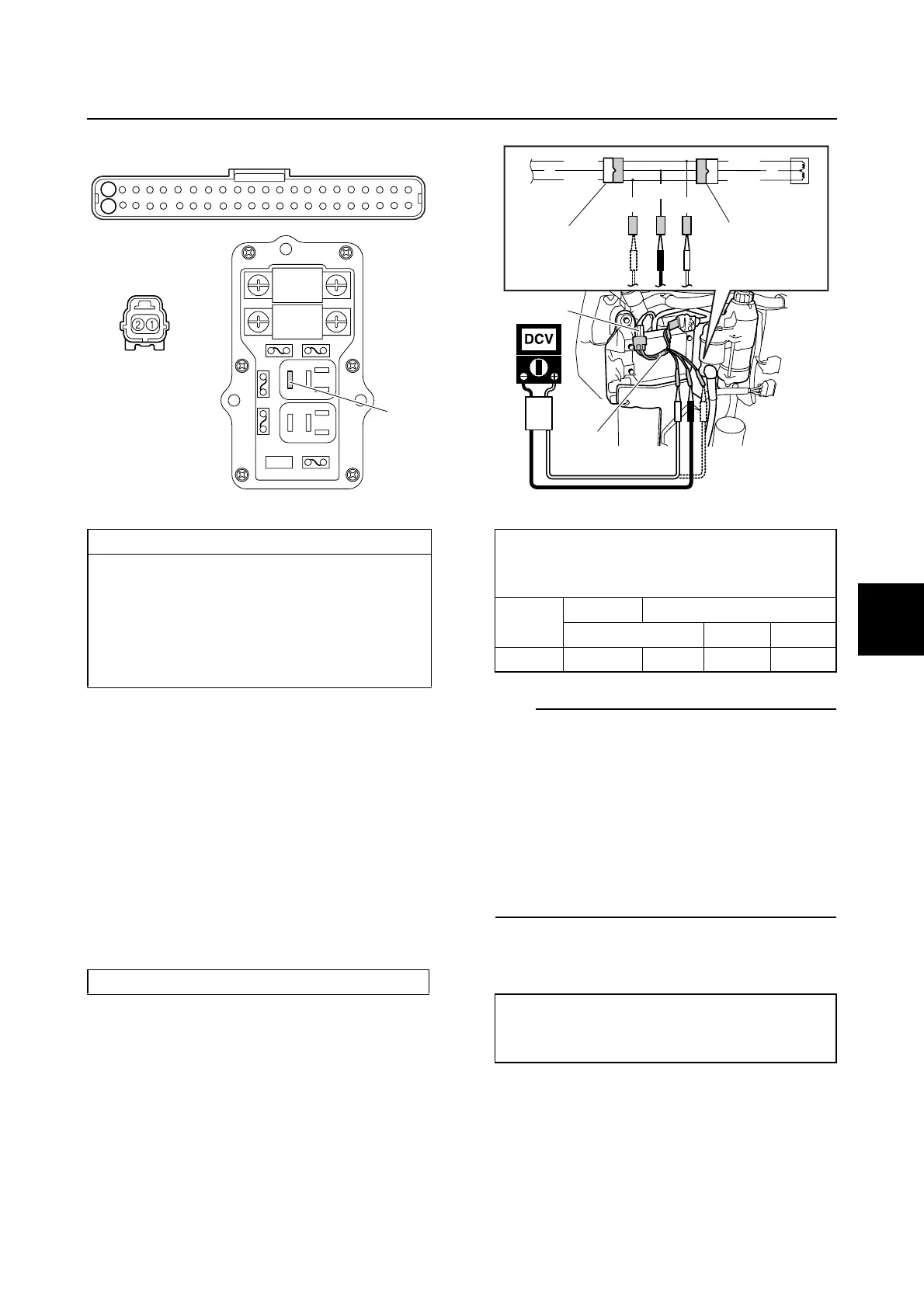
8. Install the main relay b.
9. Connect the engine ECM coupler b, and
then install the junction box cover.
10. Connect the spark plug wires and ignition
coil couplers a.
Checking the pulser coil
1. Disconnect the pulser coil coupler a,
and then connect the test harness (3
pins) a.
2. Measure the pulser coil output peak volt-
age. Replace the pulser coil if below
specification.
TIP:
• When measuring the pulser coil output
peak voltage under the unloaded cranking
condition is done, disconnect the coupler
a.
• When measuring the pulser coil output
peak voltage under the loaded cranking
condition is done, remove the clip from the
engine shut-off switch to prevent the engine
from starting.
3. Disconnect the test harness a, and then
measure the pulser coil resistance.
Wiring harness continuity:
Ignition coil #1, 4
Terminal 1–Terminal 22
Terminal 2–Terminal c
Ignition coil #2, 3
Terminal 1–Terminal 44
Terminal 2–Terminal c
Test harness (3 pins) a: 90890-06791
c
b
44
22
a
Pulser coil output peak voltage:
White/Red (W/R)–Black (B)
White/Black (W/B)–Black (B)
r/min
Unloaded Loaded
Cranking 1500 3500
DC V 3.5 3.0 21.0 39.0
Pulser coil resistance
(reference data):
459.0–561.0 Ω at 20 °C (68 °F)
B
B
W/R
W/B
W/BW/R
W/R
W/B
B
a
a
a
a