5-36
Ignition units and components
0
1
2
3
4
5
6
7
8
9
10
A
10. Connect the engine ECM coupler g, and
then install the junction box cover.
11. Connect the thermoswitch connectors.
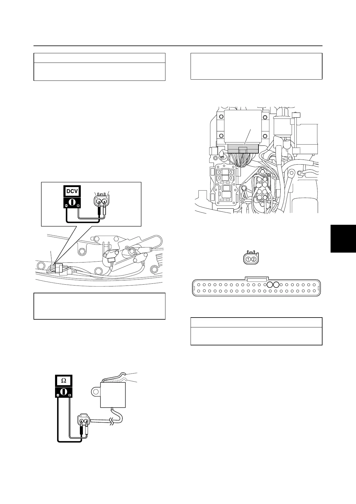
Checking the shift cut switch
1. Disconnect the shift cut switch coupler
a.
2. Turn the engine start switch to “ON,” and
then measure the input voltage.
3. Turn the engine start switch to “OFF.”
4. Remove the shift cut switch.
5. Measure the shift cut switch resistance.
6. Remove the junction box cover, and then
disconnect the engine ECM coupler d.
7. Check the wiring harness for continuity.
8. Connect the engine ECM coupler d, and
then install the junction box cover.
9. Install the shift cut switch, and then con-
nect the shift cut switch coupler a.
Wiring harness continuity:
Pink (P)–Terminal 37
Black (B)–Terminal 8
Shift cut switch input voltage:
Blue/Yellow (L/Y)–Black (B)
4.75–5.25 V
L/Y
B
a
b
c
Shift cut switch resistance:
4.465–4.935 kΩ at b position
0 Ω at c position at 20 °C (68 °F)
Wiring harness continuity:
Terminal 1–Terminal 8
Terminal 2–Terminal 9
d
8
a
d
9