5-48
PTT system
0
1
2
3
4
5
6
7
8
9
10
A
PTT system
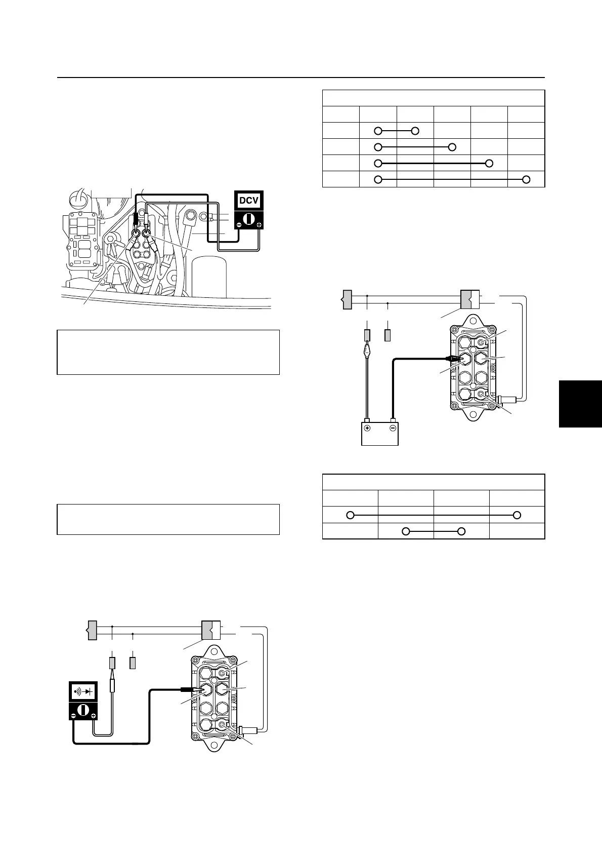
Checking the PTT relay
1. Remove the junction box cover
2. Measure the input voltage between the
PTT relay terminal a and terminal b.
3. Disconnect the battery power source,
ground lead, PTT motor leads and PTT
relay coupler. NOTICE: Always discon-
nect the battery negative terminal
before disconnecting the PTT relay
terminals.
4. Connect the test harness (2 pins) a.
5. Check the PTT relay for continuity.
Replace the PTT relay if out of specifica-
tion.
6. Connect the positive battery lead to the
terminal e, and the negative battery lead
to the terminal b, and then check the
PTT relay for continuity. Replace the PTT
relay if out of specification.
PTT relay input voltage:
Ter m ina l a–Terminal b
12.0 V (battery voltage)
Test harness (2 pins) a:
90890-06867
a
b
G/W
G
Lg
Sb
d
a
c
a
b
e
f
PTT relay continuity:
abcdef
PTT relay continuity:
abcd
G/W
G
Lg
Sb
d
c
a
b
a
f
e
Starter motor / PTT system
 Loading...


