5-17
ELEC
Electrical system
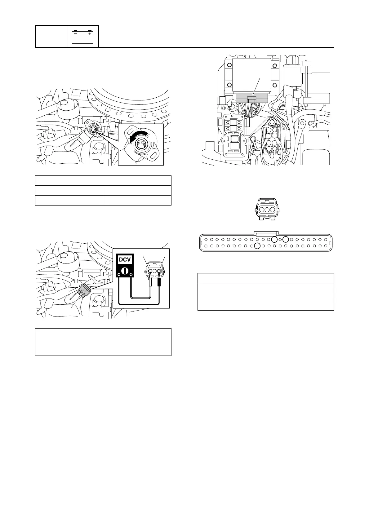
4. Remove the TPS, and then measure the
output voltages of the TPS when the sen-
sor free position c to fully turned posi-
tion d.
5. Disconnect TPS coupler e, and then
measure the TPS input voltage at the
TPS coupler.
6. Turn the engine start switch to “OFF.”
7. Remove the junction box cover, and then
disconnect the engine ECM coupler f.
8. Check the wiring harness for continuity.
9. Connect the engine ECM coupler f, and
then install the junction box cover.
10. Install the TPS, and then connect the
TPS coupler e.
Checking the ISC
1. Remove the ISC.
2. Check the proper movement of ISC valve
using the “Stationary test” of the YDIS.
TPS output voltage (reference data):
Free position c Full turn position d
0.298 V 4.980 V
TPS input voltage:
Orange (O)–Black (B)
4.75–5.25 V
c
d
e
O
B
Wiring harness continuity:
Terminal 1–Terminal 8
Terminal 2–Terminal 34
Terminal 3–Terminal 10
f
10
8
34
1
3
2
e
f