5-22
Engine control units and components
0
1
2
3
4
5
6
7
8
9
10
A
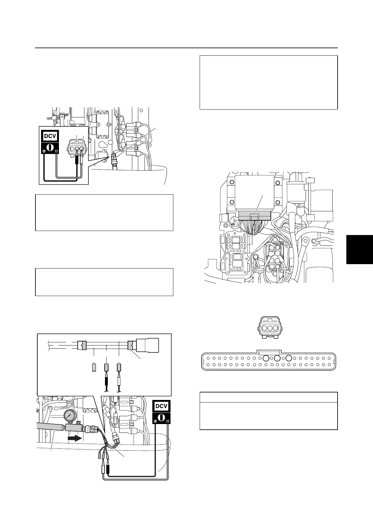
Checking the speed sensor (option)
1. Disconnect the speed sensor coupler a.
2. Turn the engine start switch to “ON,” and
then measure the input voltage at the
speed sensor coupler.
3. Remove the speed sensor, and then con-
nect the pressure pump a and test har-
ness (3 pins) b.
4. Apply positive pressure to the speed sen-
sor slowly, and then measure the output
voltage.
5. Turn the engine start switch to “OFF,” and
then disconnect the test harness b and
pressure pump a.
6. Remove the junction box cover, and then
disconnect the engine ECM coupler b.
7. Check the wiring harness for continuity.
8. Install the speed sensor, and then con-
nect the speed sensor coupler a.
9. Connect the engine ECM coupler b, and
then install the junction box cover.
Speed sensor input voltage
(reference data):
Orange (O)–Black (B)
4.75–5.25 V
Pressure pump a:
(commercially available)
Test harness (3 pins) b: 90890-06869
B
O
a
a
b
b
B
B
G
G/W
O
L
Speed sensor output voltage:
Blue (L)–Black (B)
2.5 V at 392.0 kPa
(3.92 kgf/cm
2
, 56.8 psi)
4.5 V at 784.0 kPa
(7.84 kgf/cm
2
, 113.7 psi)
Wiring harness continuity:
Terminal 1–Terminal 10
Terminal 2–Terminal 8
Terminal 3–Terminal 12
b
10
8
12
1
3
2
a
b