5-29
ELEC
Electrical system
4. Connect the spark plug wires, and then
install the spark plug wire cover.
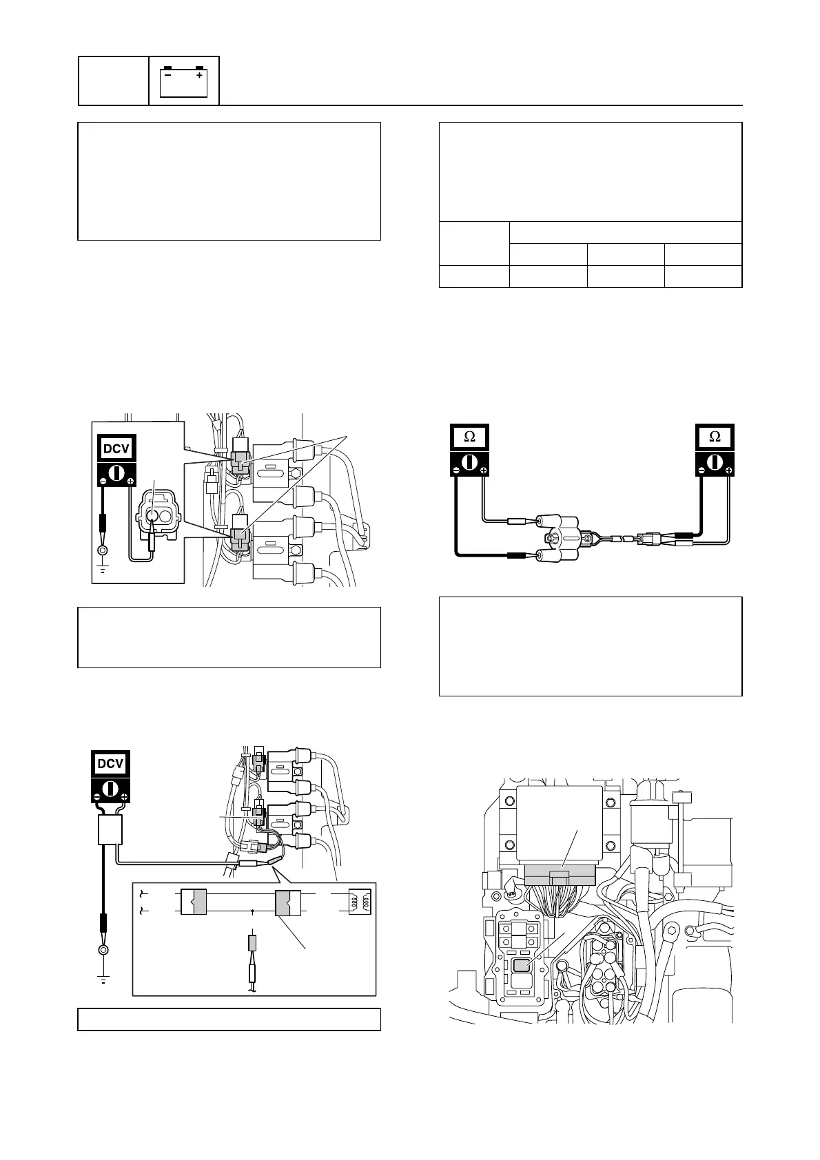
Checking the ignition coil
1. Disconnect the ignition coil couplers a.
2. Measure the input voltage at the ignition
coil coupler terminal and ground.
3. Connect the test harness (2 pins) a, and
then measure the ignition coil output
peak voltage.
4. Disconnect the test harness a and spark
plug wires from the ignition coils.
5. Measure the ignition coil resistance.
Replace if out of specification.
6. Remove the junction box cover and main
relay b, and then disconnect the engine
ECM coupler b.
7. Check the wiring harness for continuity.
Spark plug wire resistance:
#1: 4.6–10.9 kΩ
#2: 3.3–8.0 kΩ
#3: 3.8–9.3 kΩ
#4: 4.2–10.0 kΩ
at 20 °C (68 °F)
Ignition coil input voltage:
Red/Yellow (R/Y)–Ground
12.0 V (battery voltage)
Test harness (2 pins) a: 90890-06792
a
R/Y
B/W
B/W
R
R/Y
B/W
B/O
a
a
Ignition coil output peak voltage:
#1, 4
Black/Orange (B/O)–Ground
#2, 3
Black/White (B/W)–Ground
r/min
Loaded
Cranking 1500 3500
DC V 210.0 260.0 270.0
Ignition coil resistance:
A Primary coil:
1.6–2.0 Ω at 20 °C (68 °F)
B Secondary coil:
12.50–16.91 kΩ at 20 °C (68 °F)
A
B
b
b