9-36
PTT unit
0
1
2
3
4
5
6
7
8
9
10
A
13. Remove the special service tools, and
then install the manual valve and circlip.
TIP:
Quickly install the manual valve before any
fluid flows out of the hole.
14. For checking the fluid level, proceed the
step 2–step 4 again.
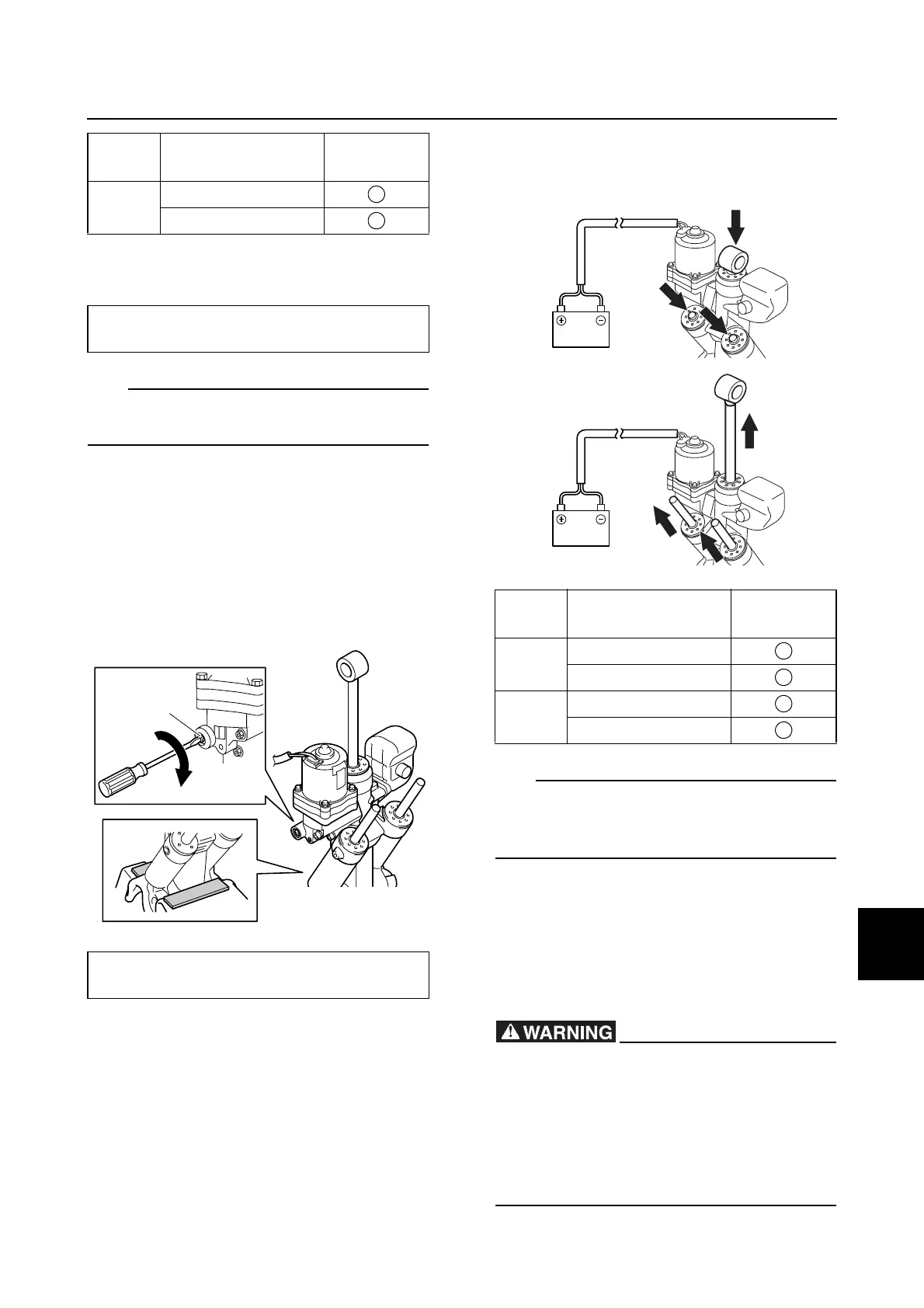
Bleeding the PTT unit
1. Place the PTT unit in an upright position.
2. Close the manual valve a by turning it
clockwise.
3. For checking the fluid level, see
“Checking the hydraulic pressure” (9-34)
step 2–step 4.
4. Connect the PTT motor leads to the
battery terminals to fully retract the PTT
rams.
5. Reverse the PTT motor leads between
the battery terminals to fully extend the
PTT rams.
TIP:
If the PTT rams do not move up and down
easily, push and pull the PTT rams to assist
operation.
6. Check the fluid level when the PTT rams
are fully extended. If the fluid level is low,
add sufficient fluid, and then repeat step
3–step 7.
Installing the PTT unit
• After tilting the swivel bracket up, make
sure to support it with the tilt stop lever.
• When installing the PTT unit with the
power unit installed, make sure to sus-
pend the outboard motor. If the outboard
motor is not suspended it can fall sud-
denly and result in severe injury.
Ram PTT motor lead
Battery
terminal
Up
Black/White (B/W)
Black (B)
Manual valve:
3.5 N·m (0.35 kgf·m, 2.58 ft·lb)
Manual valve a:
3.5 N·m (0.35 kgf·m, 2.58 ft·lb)
+
–
a
Ram PTT motor lead
Battery
terminal
Down
Black (B)
Black/White (B/W)
Up
Black/White (B/W)
Black (B)
B
B/W
BB/W
+
–
+
–