7-43
Power unit
POWR
8. If the valve seat contact area is too
narrow and situated near the top edge of
the valve face, use a 30° cutter to cut the
top edge of the valve seat, and then use
a 45° cutter to center the area and set its
width.
b
Previous contact width
9. If the valve seat contact area is too
narrow and situated near the bottom
edge of the valve face, use a 60° cutter to
cut the bottom edge of the valve seat,
and then use a 45° cutter to center the
area and set its width.
b
Previous contact width
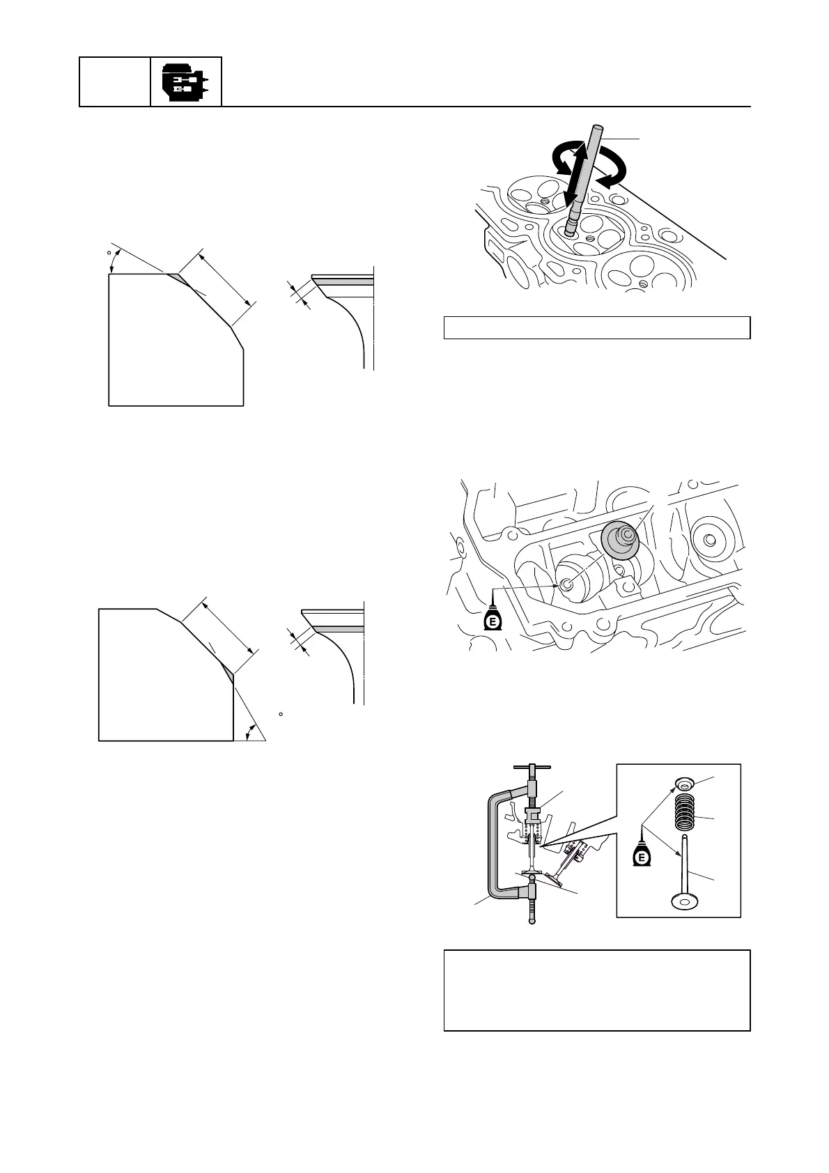
10. After refacing the valve seat to the
specified contact width, apply a thin,
even layer of lapping compound onto the
valve seat, and then lap the valve using a
special service tool a. NOTICE: Do not
get the lapping compound on the
valve stem or valve guide.
11. Check the valve seat contact area again.
See “Checking the valve seat” (7-41).
Assembling the cylinder head
1. Install a new valve seal a onto the valve
guide.
2. Install the valve b, valve spring c, and
valve spring retainer d in this order, and
then attach the special service tools e
and f.
b
30
b
60
Valve lapper a: 90890-04101
Valve spring compressor e:
90890-04019
Valve spring compressor attachment f:
90890-06320
a
a
b
c
d
e
f