7-42
Cylinder head
0
1
2
3
4
5
6
7
8
9
10
A
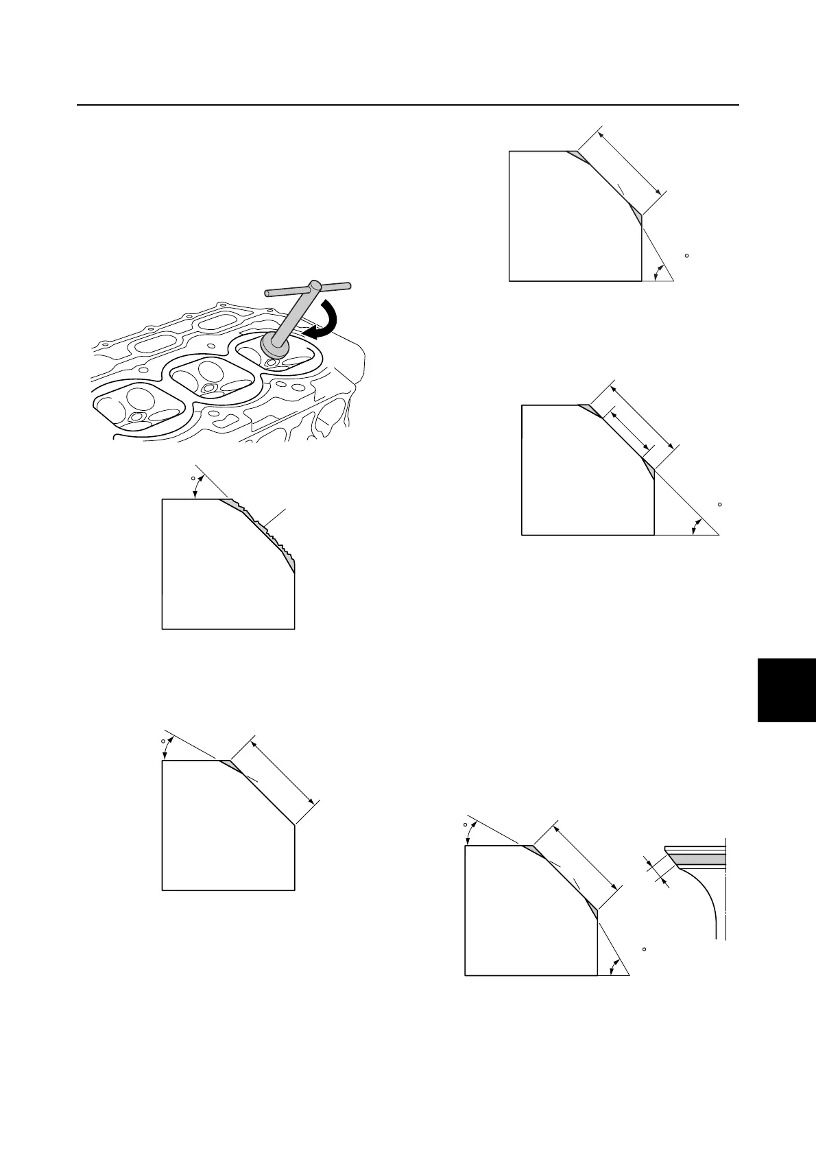
2. Cut the surface of the valve seat with a
45° cutter by turning the cutter clockwise
until the valve seat face has become
smooth. NOTICE: Do not over cut the
valve seat. Make sure to turn the
cutter evenly downward at a pressure
of 40–50 N (4.0–5.0 kgf, 8.8–11.0 lbf) to
prevent chatter marks.
a
Slag or rough surface
3. Use a 30° cutter to adjust the contact
width of the top edge of the valve seat.
b
Previous contact width
4. Use a 60° cutter to adjust the contact
width of the bottom edge of the valve
seat.
b
Previous contact width
5. Use a 45° cutter to adjust the contact
width of the valve seat to specification.
b
Previous contact width
c Specified contact width
6. Check the valve seat contact area of the
valve. See “Checking the valve seat” (7-
41).
7. If the valve seat contact area is too wide
and situated in the center of the valve
face, use a 30° cutter to cut the top edge
of the valve seat, and then use a 60°
cutter to cut the bottom edge to center
the area and set its width.
b
Previous contact width
45
a
30
b
60
b
45
b
c
b
30
60