6-23
FUEL
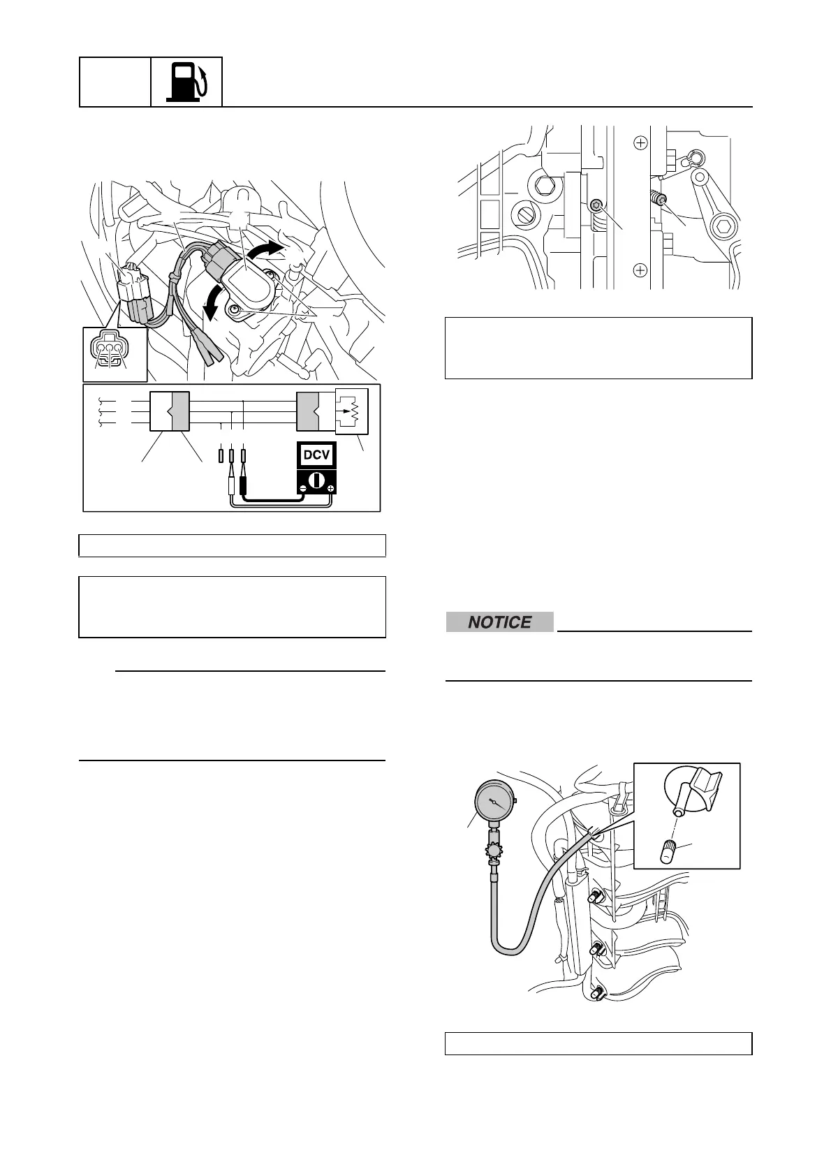
Fuel system
7. Loosen the TPS screws d and adjust the
position of the TPS e to get the specified
output voltage.
TIP:
• To increase the output voltage, turn the
TPS e in direction b.
• To decrease the output voltage, turn the
TPS e in direction c.
8. Tighten the TPS screws d.
9. Operate the throttle valves several times
and make sure that the TPS output volt-
age is specification.
10. Slowly tighten the synchronizing screw
a and stop when the TPS output voltage
begins to change.
11. Slowly tighten the throttle stop screw b,
until the TPS output voltage is within
specification.
12. Operate the throttle valves several times
and make sure that the TPS output volt-
age is within specification.
13. Adjust the throttle link. See “Adjusting the
throttle link” (6-19).
14. Install the intake silencer. See “Intake
silencer” (6-16).
Synchronizing the throttle valve
Do not adjust the throttle valves when
they are operating properly.
1. Remove the caps a, and then connect
the special service tool b to the intake
manifold.
Test harness (3 pins) c: 90890-06793
TPS output voltage:
Pink (P)–Black (B)
0.66 V
c
c
a
e
a
d
e
c
b
B
B
O
P
P
O
O
P
B
TPS output voltage:
Pink (P)–Black (B)
0.70 ± 0.02 V
Vacuum gauge b: 90890-03159
a
b
a
b
 Loading...


