7-40
Cylinder head
0
1
2
3
4
5
6
7
8
9
10
A
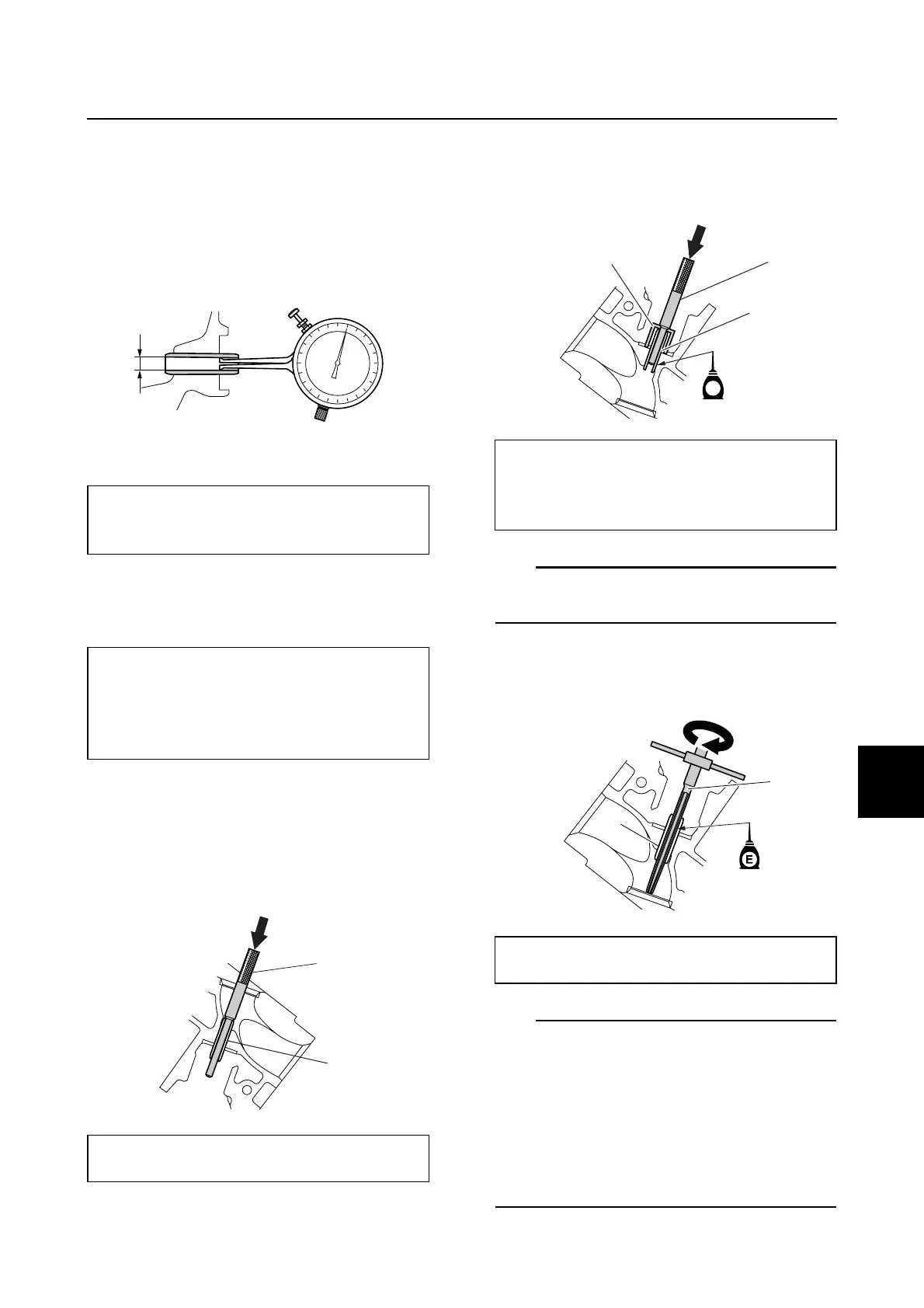
Checking the valve guide
Before checking the valve guides, make sure
that the valve stem diameter is within specifi-
cation.
1. Measure the valve guide inside diameter
a.
2. Calculate the valve stem-to-valve guide
clearance as follows. Replace the valve
guide if out of specification.
Replacing the valve guide
After replacing a valve guide, check the valve
seat contact area.
1. Remove the valve guide a using the
special service tool b from the combus-
tion chamber side.
2. Install a new valve guide c using the
special service tool b from the camshaft
side until the valve guide installer d
contacts the cylinder head.
TIP:
Apply engine oil to the outer surface of new
valve guides.
3. Insert the special service tool e into the
valve guide c, and then ream the valve
guide.
TIP:
• Apply engine oil to the inner surface of the
valve guide.
• Turn the valve guide reamer clockwise to
ream the valve guide.
• Do not turn the reamer counterclockwise
when removing it.
• Make sure to clean the valve guide after
reaming it.
Valve guide inside diameter a:
Intake and exhaust:
5.504–5.522 mm (0.2167–0.2174 in)
Valve stem-to-valve guide clearance
= valve guide inside diameter – valve
stem diameter:
Intake and exhaust:
0.025–0.058 mm (0.0010–0.0023 in)
Valve guide remover/installer b:
90890-06801
a
a
b
Valve guide remover/installer b:
90890-06801
Valve guide installer d:
90890-06810
Valve guide reamer e:
90890-06804
E
c
b
d
c
e