5-26
Charging units and components
0
1
2
3
4
5
6
7
8
9
10
A
8. Install the main relay a.
9. Connect the engine ECM coupler b, and
then install the junction box cover.
10. Connect the high-pressure fuel pump
coupler a.
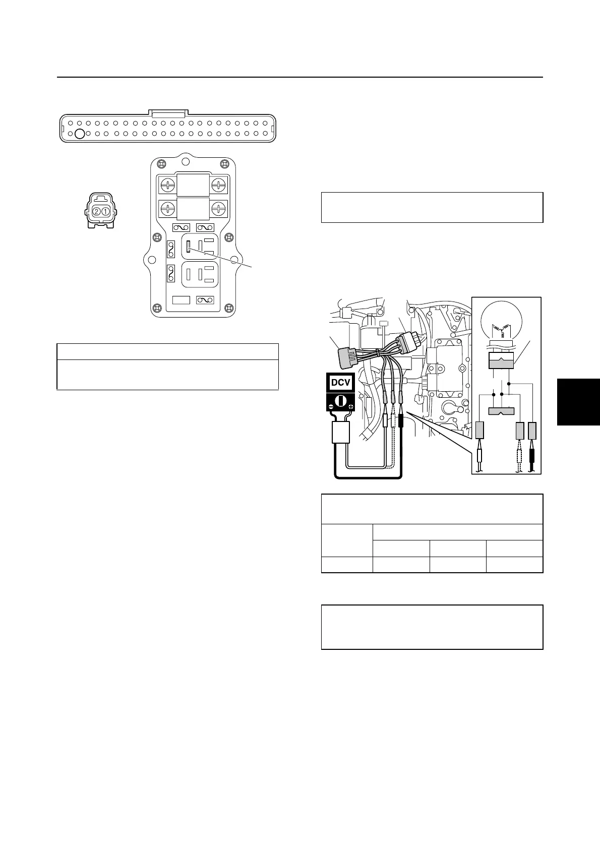
Charging units and components
Checking the lighting coil (stator
assembly)
1. Disconnect the lighting coil coupler a,
and then connect the test harness (3
pins) a.
2. Measure the lighting coil output peak
voltage between all combinations of the
terminals. Replace the lighting coil if
below specification.
3. Measure the lighting coil resistance.
4. Disconnect the test harness a, and then
connect the lighting coil coupler a.
Wiring harness continuity:
Terminal 1–Terminal c
Terminal 2–Terminal 43
c
b
43
a
Test harness (3 pins) a:
90890-06847
Lighting coil output peak voltage:
Green (G)–Green (G)
r/min
Unloaded
Cranking 1500 3500
DC V 11.0 50.0 110.0
Lighting coil resistance
(reference data):
0.2–0.3 Ω at 20 °C (68 °F)
a
a
a
G
G
G
Fuel control units and components / Charging units and components