5-50
PTT system
0
1
2
3
4
5
6
7
8
9
10
A
7. Connect the PTT relay coupler e and
PTT switch coupler a.
8. Install the junction box cover.
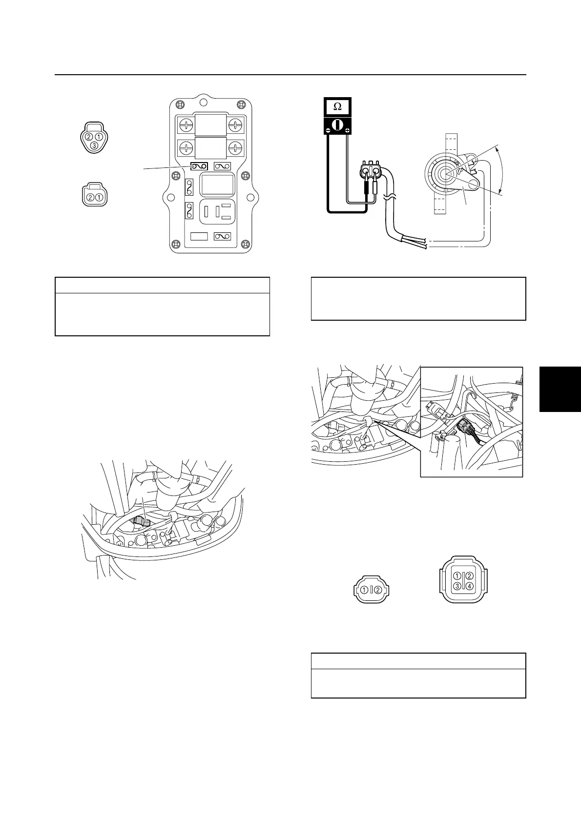
Checking the trim sensor
1. Remove the trim sensor, and then Dis-
connect the trim sensor coupler a.
2. Measure the trim sensor resistance.
3. Turn the trim sensor lever a from b to
c and measure the resistance as it grad-
ually changes.
4. Disconnect the gauge harness coupler
d.
5. Check the wiring harness for continuity.
6. Install the trim sensor.
7. Connect the gauge harness coupler d,
and trim sensor coupler a.
Wiring harness continuity:
a Terminal 1–e Terminal 1
a Terminal 2–e Terminal 2
a Terminal 3–Terminal c
f
e
a
a
Trim sensor resistance (reference data):
238.8–378.8 Ω at b
9.0–11.0 Ω at c (setting resistance)
Wiring harness continuity:
a Terminal 1–d Terminal 2
a Terminal 2–Ground
a
b
c
d
d
a
 Loading...


