6-14
Fuel filter
0
1
2
3
4
5
6
7
8
9
10
A
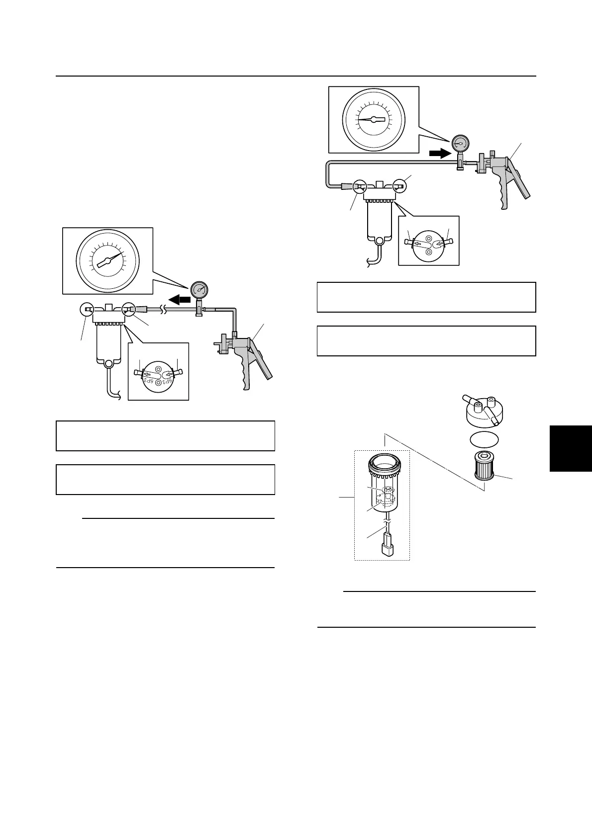
Checking the fuel filter assembly
1. Connect the vacuum/pressure pump
gauge a to the fuel inlet a.
2. Cover the fuel outlet b with a finger, and
then apply the specified positive pres-
sure. Replace the O-ring, fuel cup
assembly, or fuel filter assembly if the
specified pressure cannot be maintained
for at least 15 seconds.
TIP:
Use a commercially available vacuum/pres-
sure pump gauge a that can be pressurized
200.0 kPa (2.00 kgf/cm
2
, 29.0 psi).
3. Connect the special service tool b to the
fuel outlet b.
4. Cover the fuel inlet a with a finger, and
then apply the specified negative pres-
sure. Replace the O-ring, fuel cup
assembly, or fuel filter assembly if the
specified pressure cannot be maintained
for at least 15 seconds.
5. Disassemble the fuel filter assembly.
TIP:
Do not twist the water detection switch lead
c when removing the fuel cup assembly c.
6. Check the fuel filter element d. Replace
the fuel filter element if there is dirt or
residue.
Vacuum/pressure pump gauge a:
(commercially available)
Specified positive pressure:
200.0 kPa (2.00 kgf/cm
2
, 29.0 psi)
200
250
0
a
a
b
b
a
Vacuum/pressure pump gauge set b:
90890-06756
Specified negative pressure:
80.0 kPa (0.80 kgf/cm
2
, 11.6 psi)
6P3
6P3
0
-
100
-
80
a
b
b
a
b
c
d
e
f
c