5-49
ELEC
Electrical system
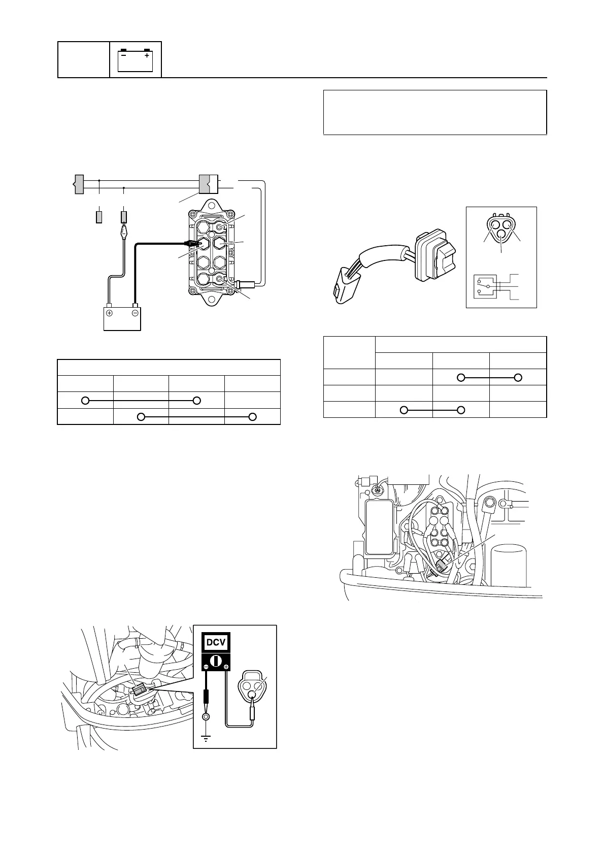
7. Connect the positive battery lead to the
terminal f, and the negative battery lead
to the terminal b, and then check the
PTT relay for continuity. Replace the PTT
relay if out of specification.
8. Connect the PTT relay coupler, battery
power source, ground lead, and PTT
motor leads.
9. Install the PTT relay and junction box
cover.
Checking the PTT switch (on bottom
cowling)
1. Disconnect the PTT switch coupler a.
2. Measure the input voltage between the
PTT switch coupler terminal and ground.
3. Check the PTT switch for continuity.
Replace the PTT switch if out of specifi-
cation.
4. Remove the junction box cover.
5. Disconnect the PTT relay coupler e.
6. Check the wiring harness for continuity.
PTT relay continuity:
abcd
G/W
G
Lg
Sb
c
a
d
b
a
f
e
a
R
PTT switch input voltage:
Red (R)–Ground
12.0 V (battery voltage)
Switch
position
Terminal
bcd
UP
Free
DN
Lg
R
Sb
c
d
b
e
 Loading...


