5-23
ELEC
Electrical system
Fuel control units and
components
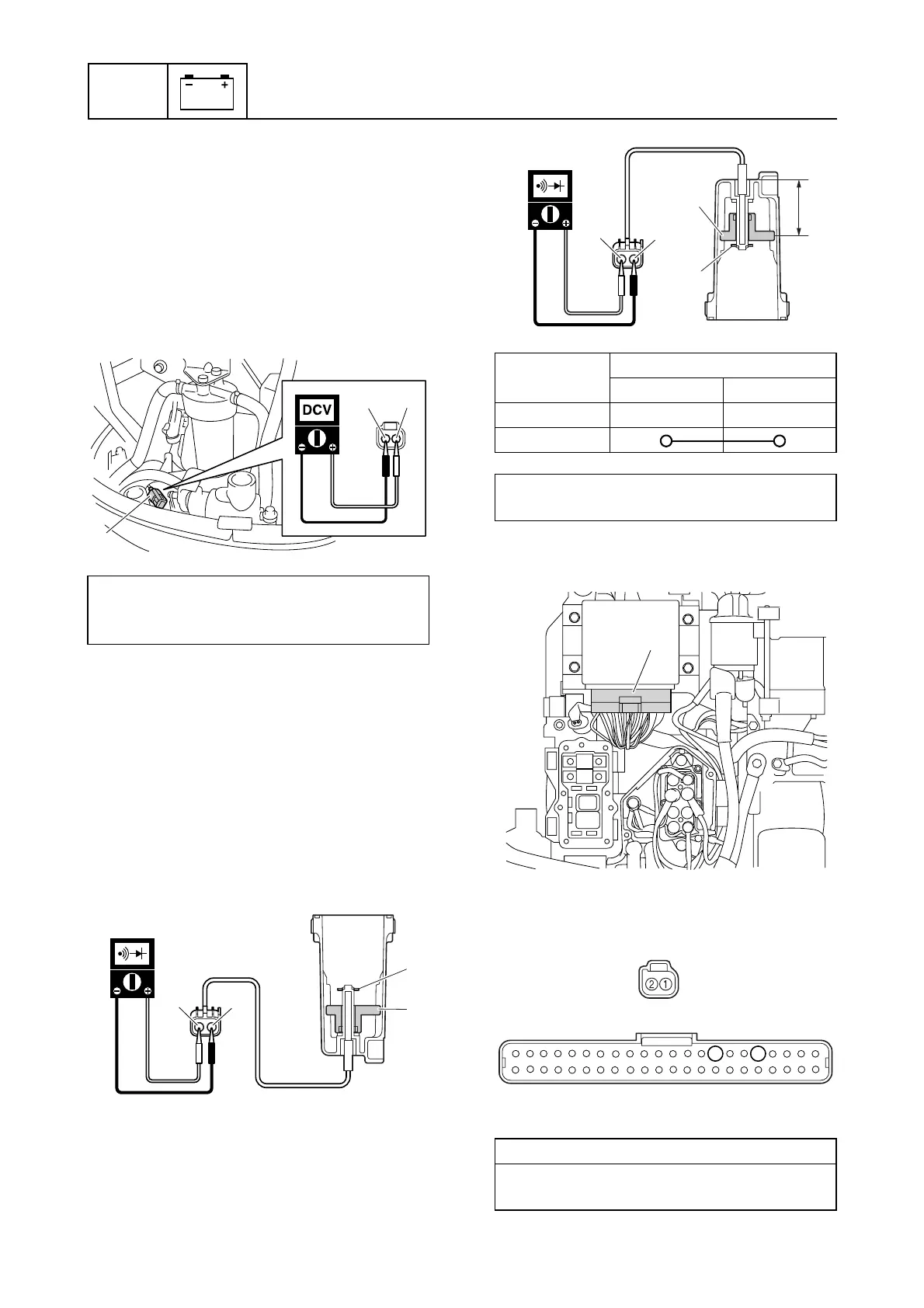
Checking the water detection switch
1. Disconnect the water detection switch
coupler a.
2. Turn the engine start switch to “ON,” and
then measure the input voltage at the
water detection switch coupler.
3. Turn the engine start switch to “OFF,” and
then remove the filter cup assembly.
4. Before checking the water detection
switch, make sure that the float a is able
to move smoothly.
5. Check the water detection switch for conti-
nuity with the float in positions A and B .
NOTICE: Make sure not to remove the
clip b and float a.
6. Remove the junction box cover, and then
disconnect the engine ECM coupler e.
7. Check the wiring harness for continuity.
Water detection switch input voltage:
Blue/White (L/W)–Black (B)
4.75–5.25 V
L/W
B
a
b
b
a
A
c
Float
position
Terminal
bc
A
B
Float height d (reference data):
40.0 mm (1.57 in)
Wiring harness continuity:
Terminal 1–Terminal 5
Terminal 2–Terminal 8
a
B
b
d
b
c
e
8
a
e
5