5-18
Engine control units and components
0
1
2
3
4
5
6
7
8
9
10
A
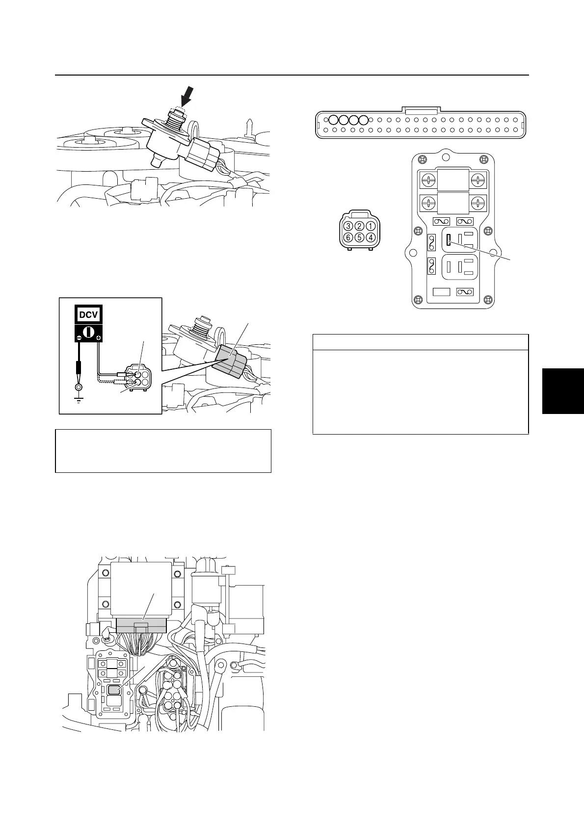
3. Disconnect the ISC coupler a.
4. Turn the engine start switch to “ON,” and
then measure the ISC input voltage at
the ISC coupler terminal and ground.
5. Turn the engine start switch to “OFF.”
6. Remove the junction box cover and the
main relay a, and then disconnect the
engine ECM coupler b.
7. Check the wiring harness for continuity.
8. Install the main relay a.
9. Connect the engine ECM coupler b, and
then install the junction box cover.
10. Connect the ISC coupler a.
ISC input voltage:
Red/Yellow (R/Y)–Ground
12.0 V (battery voltage)
a
R/Y
R/Y
b
a
Wiring harness continuity:
Terminal 1–Terminal 20
Terminal 2–Terminal c
Terminal 3–Terminal 18
Terminal 4–Terminal 21
Terminal 5–Terminal c
Terminal 6–Terminal 19
a
20
c
b
21
18
19