7-24
Power unit assembly
0
1
2
3
4
5
6
7
8
9
10
A
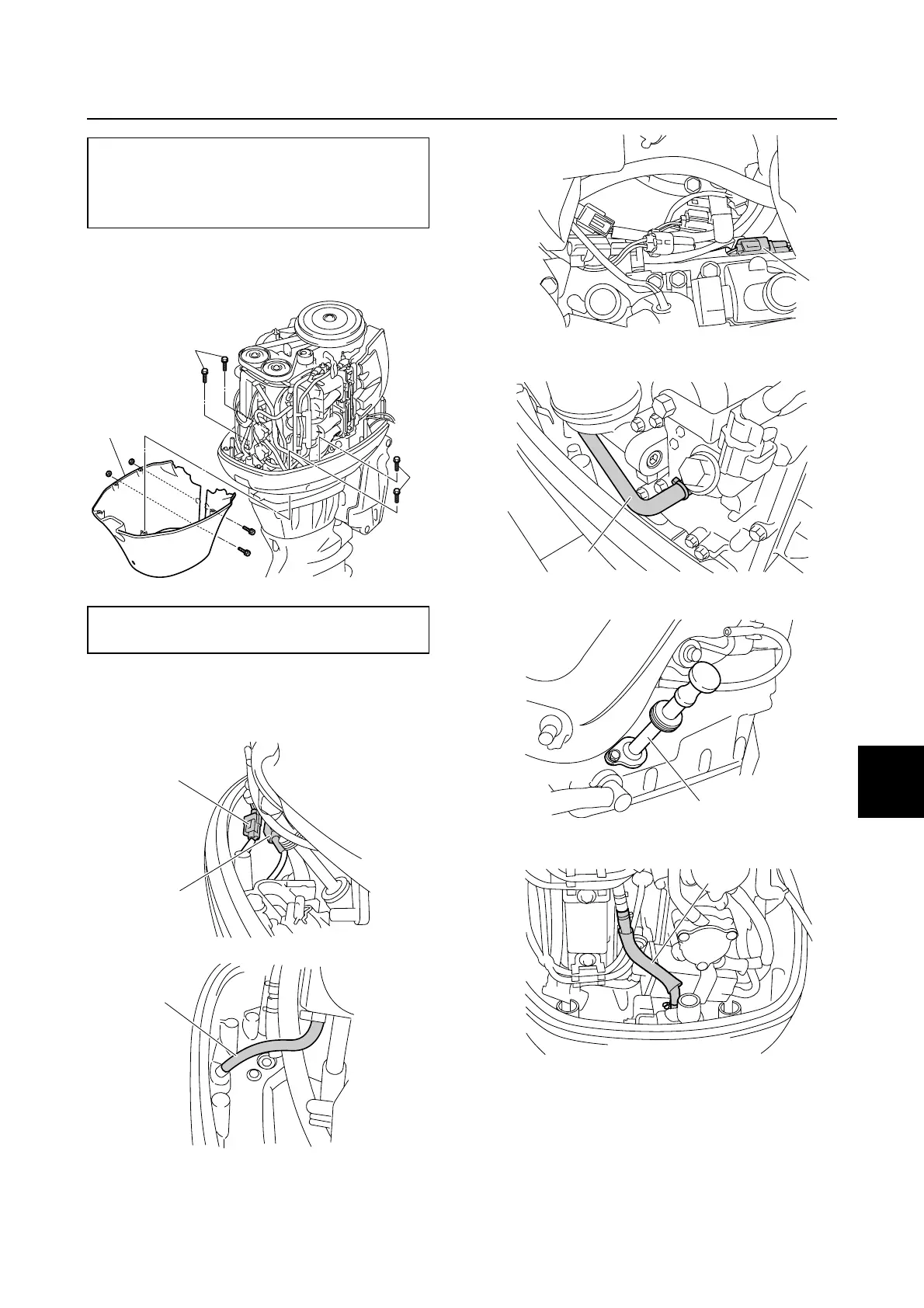
3. Install the apron f, and then tightening
the bolts g to the specified torque.
4. Connect the shift cut switch coupler a,
neutral switch coupler b and cooling
water pilot hose h.
5. Connect the PTT switch coupler c.
6. Connect the flushing hose i.
7. Install the dipstick guide j.
8. Connect the vapor gas hose k.
Bolt (M8) c:
20 N·m (2.0 kgf·m, 14.8 ft·lb)
Bolt (M10) d and e:
42 N·m (4.2 kgf·m, 31.0 ft·lb)
Bolt g:
4 N·m (0.4 kgf·m, 3.0 ft·lb)
f
g
g
b
a
h
c
i
j
k