B.3 Parameter Table
420 YASKAWA ELECTRIC SIEP C710616 27C YASKAWA AC Drive A1000 Technical Manual
■ F2: Analog Input Card (AI-A3)
■ F3: Digital Input Card (DI-A3)
■ F4: Analog Monitor Card (AO-A3)
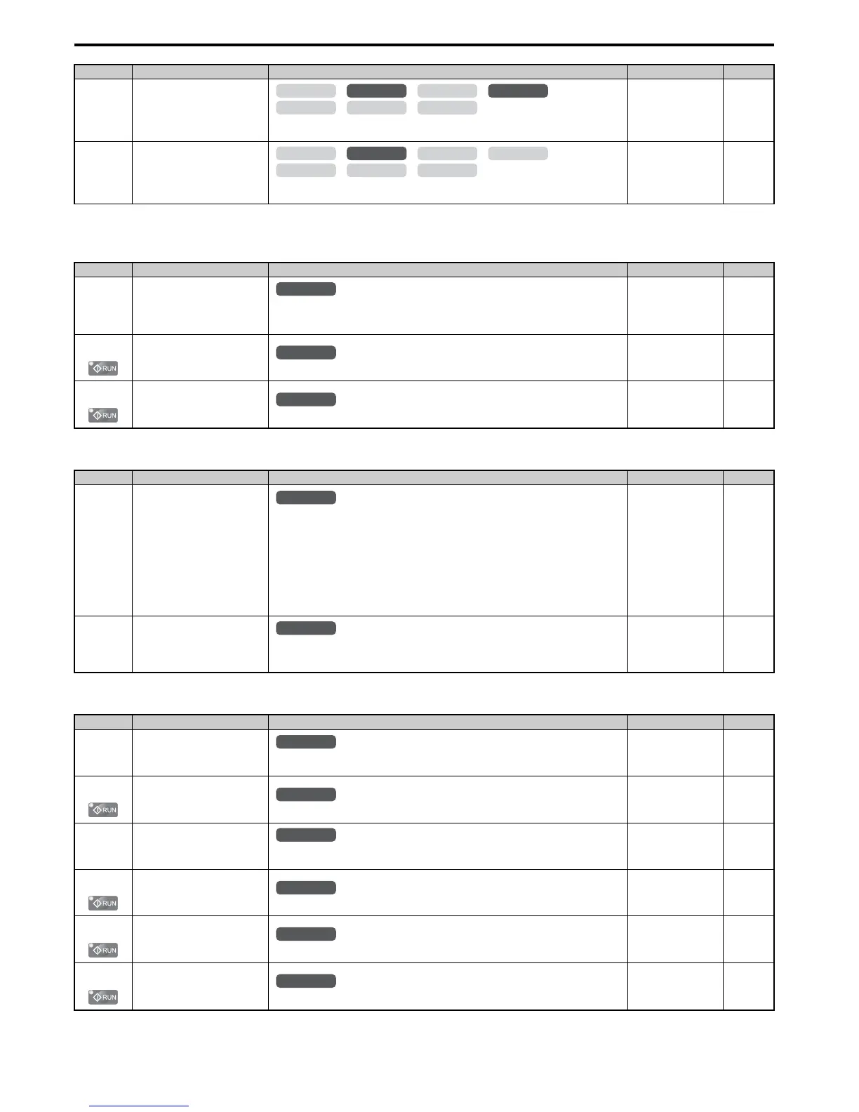
F1-36
(3B5H)
PG Option Card Disconnect
Detection 2
0: Disabled
1: Enabled
Default: 1
Min: 0
Max: 1
208
F1-37
(3BDH)
PG 2 Signal Selection
0: A pulse detection
1: AB pulse detection
Default: 0
Min: 0
Max: 1
208
<10> Default setting is determined by the control mode (A1-02).
No.(Addr.) Name Description Setting Page
F2-01
(38FH)
Analog Input Option Card
Operation Selection
0: Option card input terminals V1, V2, and V3 replace drive input terminals A1, A2, and A3.
1: Input signals to terminals V1, V2, and V3 are added together to create the frequency
reference.
Default: 0
Min: 0
Max: 1
209
F2-02
(368H)
Analog Input Option Card Gain
Sets the gain for the input signal to the analog card.
Default: 100.0%
Min: -999.9%
Max: 999.9%
209
F2-03
(369H)
Analog Input Option Card Bias
Sets the bias for the input signal to the analog card.
Default: 0.0%
Min: -999.9%
Max: 999.9%
209
No.(Addr.) Name Description Setting Page
F3-01
(390H)
Digital Input Option Card Input
Selection
0: BCD, 1% units
1: BCD, 0.1% units
2: BCD, 0.01% units
3: BCD, 1 Hz units
4: BCD, 0.1 Hz units
5: BCD, 0.01 Hz units
6: BCD customized setting (5 digit), 0.02 Hz units
7: Binary input
When the digital operator units are set to be displayed in Hertz or user-set units (o1-03 = 2 or 3),
the units for F3-01 are determined by parameter o1-03.
Default: 0
Min: 0
Max: 7
209
F3-03
(3B9H)
Digital Input Option DI-A3 Data
Length Selection
0: 8 bit
1: 12 bit
2: 16 bit
Default: 2
Min: 0
Max: 2
210
No.(Addr.) Name Description Setting Page
F4-01
(391H)
Terminal V1 Monitor Selection
Sets the monitor signal for output from terminal V1. Set this parameter to the last three digits of
the desired U- monitor. Some U parameters are available only in certain control modes.
Default: 102
Min: 000
Max: 999
210
F4-02
(392H)
Terminal V1 Monitor Gain
Sets the gain for voltage output via terminal V1.
Default: 100.0%
Min: -999.9%
Max: 999.9%
210
F4-03
(393H)
Terminal V2 Monitor Selection
Sets the monitor signal for output from terminal V2. Set this parameter to the last three digits of
the desired U- monitor. Some U parameters are available only in certain control modes.
Default: 103
Min: 000
Max: 999
210
F4-04
(394H)
Terminal V2 Monitor Gain
Sets the gain for voltage output via terminal V2.
Default: 50.0%
Min: -999.9%
Max: 999.9%
210
F4-05
(395H)
Terminal V1 Monitor Bias
Sets the amount of bias added to the voltage output via terminal V1.
Default: 0.0%
Min: -999.9%
Max: 999.9%
210
F4-06
(396H)
Terminal V2 Monitor Bias
Sets the amount of bias added to the voltage output via terminal V2.
Default: 0.0%
Min: -999.9%
Max: 999.9%
210
No.(Addr.) Name Description Setting Page
OLV/PM AOLV/PM
CLV
V/f w/PG
CLV/PM
V/f OLV

 Loading...


