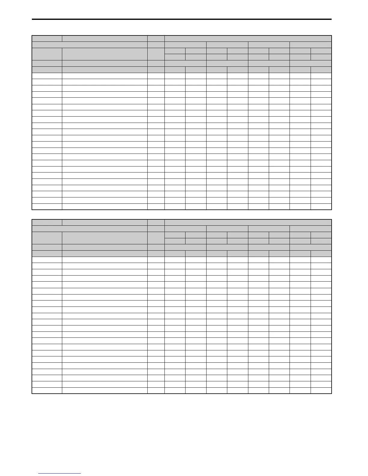
B.6 Defaults by Drive Model Selection (o2-04) and ND/HD (C6-01)
460 YASKAWA ELECTRIC SIEP C710616 27C YASKAWA AC Drive A1000 Technical Manual
No. Name Unit Default Settings
Model CIMR-A – 4A0009 4A0011 4A0018 4A0023
C6-01 Drive Duty Selection –
HD ND HD ND HD ND HD ND
0 1 0 1 0 1 0 1
o2-04 Drive Model Selection Hex. 96 97 99 9A
E2-11 (E4-11) Motor rated Output kW 3.0 3.7 3.7 5.5 5.5 7.5 7.5 11
b3-04 V/f Gain during Speed Search % 100 100 100 100 100 100 100 100
b3-06 Output Current 1 during Speed Search – 0.5 0.5 0.5 0.5 0.5 0.5 0.5 0.5
b8-03 Energy Saving Control Filter Time Constant s 0.50 0.50 0.50 0.50 0.50 0.50 0.50 0.50
b8-04 Energy Saving Coefficient Value – 265.7 245.8 245.8 189.5 189.5 145.38 145.38 140.88
C5-17 (C5-37) Motor Inertia
kgm
2
0.0158 0.0158 0.0158 0.0255 0.026 0.037 0.037 0.053
C6-02 Carrier Frequency Selection – 1 7 1 7 1 7 1 7
E2-01 (E4-01) Motor Rated Current A 5.7 7 7 9.8 9.8 13.3 13.3 19.9
E2-02 (E4-02) Motor Rated Slip Hz 2.7 2.7 2.7 1.5 1.5 1.3 1.3 1.7
E2-03 (E4-03) Motor No-Load Current A 1.9 2.3 2.3 2.6 2.6 4 4 5.6
E2-05 (E4-05) Motor Line to Line Resistance Ω 4.360 3.333 3.333 1.595 1.595 1.152 1.152 0.922
E2-06 (E4-06) Motor Leakage Inductance % 19 19.3 19.3 18.2 18.2 15.5 15.5 19.6
E2-10 (E4-10) Motor Iron Loss for Torque Compensation W 105 130 130 193 193 263 263 385
E5-01 Motor Code Selection Hex. FFFF FFFF 1238 1238 123A 123A 123B 123B
L2-02 Momentary Power Loss Ride-Thru Time s 0.5 0.5 0.5 0.5 0.8 0.8 1 1
L2-03 Momentary Power Loss Minimum Baseblock Time s 0.5 0.6 0.6 0.7 0.7 0.8 0.8 0.9
L2-04 Momentary Power Loss Voltage Recovery Time s 0.3 0.3 0.3 0.3 0.3 0.3 0.3 0.3
L3-24 Motor Acceleration Time for Inertia Calculations s 0.145 0.154 0.154 0.168 0.168 0.175 0.175 0.265
L8-02 Overheat Alarm Level °C 110 110 110 110 110 110 115 115
L8-35 Installation Method Selection – 2 2 2 2 2 2 2 2
L8-38 Carrier Frequency Reduction Selection – 2 2 2 2 2 2 2 2
n1-03 Hunting Prevention Time Constant ms 10 10 10 10 10 10 10 10
n5-02 Motor Acceleration Time s 0.145 0.154 0.154 0.168 0.168 0.175 0.175 0.265
No. Name Unit Default Settings
Model CIMR-A – 4A0031 4A0038 4A0044 4A0058
C6-01 Drive Duty Selection –
HD ND HD ND HD ND HD ND
0 1 0 1 0 1 0 1
o2-04 Drive Model Selection Hex. 9C 9D 9E 9F
E2-11 (E4-11) Motor rated Output kW 11 15 15 18.5 18.5 22 22 30
b3-04 V/f Gain during Speed Search % 100 100 100 100 100 100 100 100
b3-06 Output Current 1 during Speed Search – 0.5 0.5 0.5 0.5 0.5 0.5 0.5 0.5
b8-03 Energy Saving Control Filter Time Constant s 0.50 0.50 0.50 0.50 0.50 0.50 0.50 0.50
b8-04 Energy Saving Coefficient Value – 140.88 126.26 126.26 115.74 115.74 103.58 103.58 92.54
C5-17 (C5-37) Motor Inertia
kgm
2
0.053 0.076 0.076 0.138 0.138 0.165 0.165 0.220
C6-02 Carrier Frequency Selection – 1 7 1 7 1 7 1 7
E2-01 (E4-01) Motor Rated Current A 19.9 26.5 26.5 32.9 32.9 38.6 38.6 52.3
E2-02 (E4-02) Motor Rated Slip Hz 1.7 1.6 1.6 1.67 1.67 1.7 1.7 1.8
E2-03 (E4-03) Motor No-Load Current A 5.6 7.6 7.6 7.8 7.8 9.2 9.2 10.9
E2-05 (E4-05) Motor Line to Line Resistance Ω 0.922 0.55 0.55 0.403 0.403 0.316 0.316 0.269
E2-06 (E4-06) Motor Leakage Inductance % 19.6 17.2 17.2 20.1 20.1 23.5 23.5 20.7
E2-10 (E4-10) Motor Iron Loss for Torque Compensation W 385 440 440 508 508 586 586 750
E5-01 Motor Code Selection Hex. 123D 123D 123E 123E 123F 123F 1240 1240
L2-02 Momentary Power Loss Ride-Thru Time s 2 2 2 2 2 2 2 2
L2-03 Momentary Power Loss Minimum Baseblock Time s 0.9 1 1 1 1 1 1 1.1
L2-04 Momentary Power Loss Voltage Recovery Time s 0.3 0.6 0.6 0.6 0.6 0.6 0.6 0.6
L3-24 Motor Acceleration Time for Inertia Calculations s 0.265 0.244 0.244 0.317 0.317 0.355 0.355 0.323
L8-02 Overheat Alarm Level °C 120 120 120 120 115 115 120 120
L8-35 Installation Method Selection – 2 2 2 2 2 2 0 0
L8-38 Carrier Frequency Reduction Selection – 2 2 2 2 2 2 2 2
n1-03 Hunting Prevention Time Constant ms 10 10 10 10 10 10 10 10
n5-02 Motor Acceleration Time s 0.265 0.244 0.244 0.317 0.317 0.355 0.355 0.323

 Loading...


