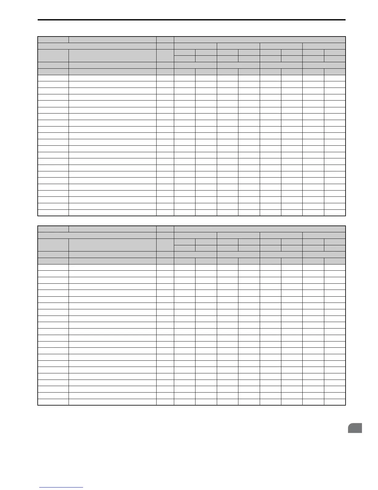
No. Name Unit Default Settings
Model CIMR-A – 4A0072 4A0088 4A0103 4A0139
C6-01 Drive Duty Selection –
HD ND HD ND HD ND HD ND
0 1 0 1 0 1 0 1
o2-04 Drive Model Selection Hex. A1 A2 A3 A4
E2-11 (E4-11) Motor rated Output kW 30 37 37 45 45 55 55 75
b3-04 V/f Gain during Speed Search % 100 100 100 100 100 80 80 60
b3-06 Output Current 1 during Speed Search – 0.5 0.5 0.5 0.5 0.5 0.5 0.5 0.7
b8-03 Energy Saving Control Filter Time Constant s 0.50 0.50 0.50 0.50 0.50 2.00 2.00 2.00
b8-04 Energy Saving Coefficient Value – 92.54 76.32 76.32 71.56 71.56 67.2 67.2 46.2
C5-17 (C5-37) Motor Inertia
kgm
2
0.220 0.273 0.273 0.333 0.333 0.490 0.49 0.90
C6-02 Carrier Frequency Selection – 1 7 1 7 1 7 1 7
E2-01 (E4-01) Motor Rated Current A 52.3 65.6 65.6 79.7 79.7 95 95 130
E2-02 (E4-02) Motor Rated Slip Hz 1.8 1.33 1.33 1.6 1.6 1.46 1.46 1.39
E2-03 (E4-03) Motor No-Load Current A 10.9 19.1 19.1 22 22 24 24 36
E2-05 (E4-05) Motor Line to Line Resistance Ω 0.269 0.155 0.155 0.122 0.122 0.088 0.088 0.092
E2-06 (E4-06) Motor Leakage Inductance % 20.7 18.8 18.8 19.9 19.9 20 20 20
E2-10 (E4-10) Motor Iron Loss for Torque Compensation W 750 925 925 1125 1125 1260 1260 1600
E5-01 Motor Code Selection Hex. 1242 1242 1243 1243 1244 1244 1245 1245
L2-02 Momentary Power Loss Ride-Thru Time s 2 2 2 2 2 2 2 2
L2-03 Momentary Power Loss Minimum Baseblock Time s 1.1 1.1 1.1 1.2 1.2 1.2 1.2 1.3
L2-04 Momentary Power Loss Voltage Recovery Time s 0.6 0.6 0.6 0.6 0.6 1 1 1
L3-24 Motor Acceleration Time for Inertia Calculations s 0.323 0.32 0.32 0.387 0.387 0.317 0.317 0.533
L8-02 Overheat Alarm Level °C 120 120 110 110 120 120 130 130
L8-35 Installation Method Selection – 0 0 0 0 0 0 0 0
L8-38 Carrier Frequency Reduction Selection –22222222
n1-03 Hunting Prevention Time Constant ms 10 10 10 10 10 10 30 30
n5-02 Motor Acceleration Time s 0.323 0.32 0.32 0.387 0.387 0.317 0.317 0.533
No. Name Unit Default Settings
Model CIMR-A – 4A0165 4A0208 4A0250 4A0296
C6-01 Drive Duty Selection –
HD ND HD ND HD ND HD ND
0 1 0 1 0 1 0 1
o2-04 Drive Model Selection Hex. A5 A6 A7 A8
E2-11 (E4-11) Motor rated Output kW 75 90 90 110 110 132 132 160
b3-04 V/f Gain during Speed Search % 60 60 60 60 60 60 60 60
b3-06 Output Current 1 during Speed Search – 0.7 0.7 0.7 0.7 0.7 0.7 0.7 0.7
b8-03 Energy Saving Control Filter Time Constant s 2.00 2.00 2.00 2.00 2.00 2.00 2.00 2.00
b8-04 Energy Saving Coefficient Value – 46.2 38.91 38.91 36.23 36.23 32.79 32.79 30.13
C5-17 (C5-37) Motor Inertia
kgm
2
0.90 1.10 1.10 1.90 1.90 2.10 2.10 3.30
C6-02 Carrier Frequency Selection – 1 7 1 7 1 7 1 7
E2-01 (E4-01) Motor Rated Current A 130 156 156 190 190 223 223 270
E2-02 (E4-02) Motor Rated Slip Hz 1.39 1.4 1.4 1.4 1.4 1.38 1.38 1.35
E2-03 (E4-03) Motor No-Load Current A 36 40 40 49 49 58 58 70
E2-05 (E4-05) Motor Line to Line Resistance Ω 0.092 0.056 0.056 0.046 0.046 0.035 0.035 0.029
E2-06 (E4-06) Motor Leakage Inductance % 20 20 20 20 20 20 20 20
E2-10 (E4-10) Motor Iron Loss for Torque Compensation W 1600 1760 1760 2150 2150 2350 2350 2850
E5-01 Motor Code Selection Hex. 1246 1246 1247 1247 1248 1248 1249 1249
L2-02 Momentary Power Loss Ride-Thru Time s 2 2 2 2 2 2 2 2
L2-03 Momentary Power Loss Minimum Baseblock Time s 1.3 1.5 1.5 1.7 1.7 1.7 1.7 1.8
L2-04 Momentary Power Loss Voltage Recovery Times11111111
L3-24 Motor Acceleration Time for Inertia Calculations s 0.533 0.592 0.592 0.646 0.646 0.673 0.673 0.777
L8-02 Overheat Alarm Level °C 130 130 120 120 120 120 125 125
L8-35 Installation Method Selection – 0 0 0 0 0 0 0 0
L8-38 Carrier Frequency Reduction Selection –22222222
n1-03 Hunting Prevention Time Constant ms 30 30 30 30 30 30 30 30
n5-02 Motor Acceleration Time s 0.533 0.592 0.592 0.646 0.646 0.673 0.673 0.777

 Loading...


