5.4 Settings That Must Be Adjusted to the System
5.4.4 Movement Method and Coordinate Settings
5-27
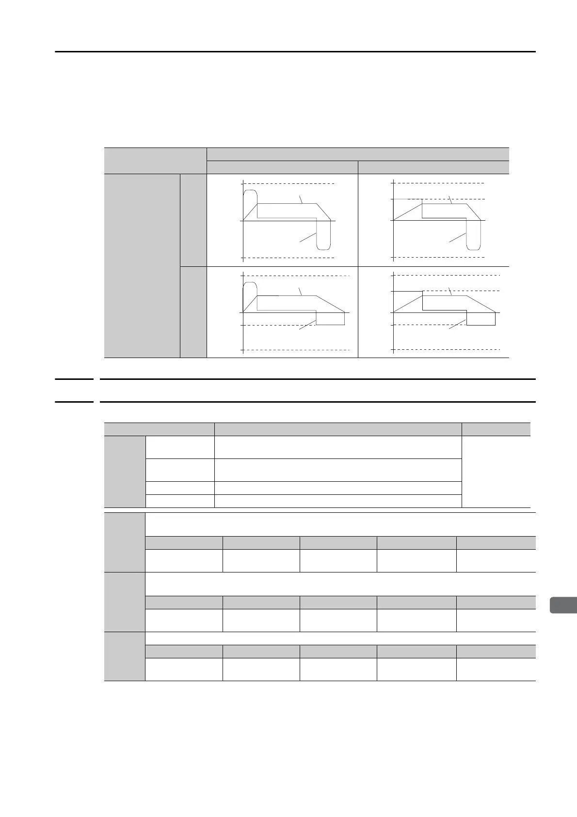
Changes in the Output Torque for External To rq u e L i m i ts
The following table shows the changes in the output torque when the internal torque limit is set
to 800%.
In this example, the Servomotor direction is set to Pn000 = n.0 (Use CCW as the forward
direction).
5.4.4
Movement Method and Coordinate Settings
Use the following parameters to set the movement method and the coordinates.
/P-CL signal
OFF ON
/N-CL signal
OFF
ON
Pn403
0
Pn404
Pn402
Torque
Speed
0
Pn403
Pn405
Pn402
Torque
Speed
0
Pn403
Pn405
Pn404
Pn402
Torque
Speed
Parameter Meaning When Enabled
PnB20
0
[default setting]
Use linear coordinates.
After restart
1
Use rotational coordinates. Use the shortest path (automati-
cally set the shortest direction).
2 Use rotational coordinates. Always move forward.
3 Use rotational coordinates. Always move in reverse.
PnB21
Linear coordinates (PnB20 = 0): Forward Software Limit (P-LS)
Rotational coordinates (PnB20 ≠ 0): Last Rotational Coordinate
Setting Range Setting Unit Default Setting When Enabled Classification
-99,999,999 to
99,999,999
Reference units 99,999,999 After restart Setup
PnB23
Linear coordinates (PnB20 = 0): Reverse Software Limit (N-LS)
Rotational coordinates (PnB20 ≠ 0): First Rotational Coordinate
Setting Range Setting Unit Default Setting When Enabled Classification
-99,999,999 to
99,999,999
Reference units -99,999,999 After restart Setup
PnB25
Home Position
Setting Range Setting Unit Default Setting When Enabled Classification
-99,999,999 to
99,999,999
Reference units 0 After restart Setup
 Loading...


