7.3 Program Table Operation
7.3.7 Program Table Operation Examples
7-34
7.3.7
Program Table Operation Examples
This section provides examples of positioning operation to show the timing of the I/O signals
related to program table operation.
In the following examples, it is assumed that homing has been completed to define the home
position.
Refer to the following section for a timing chart from when the power supply is turned ON until
homing is completed.
7.2
Homing
on page 7-3
Positioning Operation Example
Executing Program Steps with the Program Step Selection Inputs
In this example, positioning is performed for program steps 3 and 5.
Step 3 performs relative positioning for 100,000 reference units at a speed of 15,000 refer-
ences units/s with a positioning completed width of 10 reference units.
Step 5 performs relative positioning for 300,000 reference units at a speed of 30,000 refer-
ences units/s with a positioning completed width of 10 reference units.
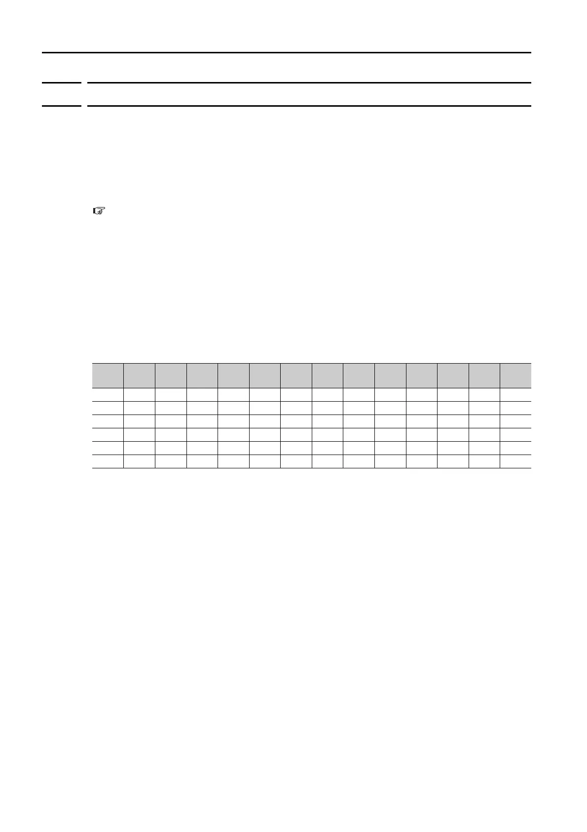
The program table for these positioning operations is shown below.
• Operating Procedure
Turn ON the /MODE signal to change to mode 0.
Set the /SEL0 to /SEL5 signals to 3 to specify program step 3.
Turn ON the /START signal to start program table operation.
The /POUT0 to /POUT5 signals output 3.
Keep the /START signal ON for at least 2 ms and then confirm that the /BUSY signal is ON.
If the /BUSY signal is ON, turn OFF the /START signal.
When positioning is completed to the target position, the /INPOSITION signal turns ON.
Set the /SEL0 to /SEL5 signals to 5 to specify program step 5.
Turn ON the /START signal to start program table operation.
The /POUT0 to /POUT5 signals output 5.
Keep the /START signal ON for at least 2 ms and then confirm that the /BUSY signal is ON.
If the /BUSY signal is ON, turn OFF the /START signal.
When positioning is completed to the target position, the /INPOSITION signal turns ON.
PGM-
STEP
POS SPD ACC DEC TLIMT
PTLIMT
CLLV PSPD
INPOS AREA1 AREA2 EVENT
NEXT
0
I+100000
15000
400000 200000
: – 0 2000 10 0 0
IT1000
END
1
A+100000
15000 : : : – 0 2000 20 0 0
IT2000
END
2
I+300000
15000 : : 30 – 0 2000 10 0 0
IT3000
END
3
I+100000
15000 : : : – 0 2000 : 0 0
IT2000
END
4
I+200000
30000
200000
: : – 0 2000 : 0 0
IT2000
END
5
I+300000
30000
400000
: 100 – 0 2000 : 0 0
IT2000
END
 Loading...


