7.5 ZONE Outputs
7.5.1 ZONE Table and ZONE Signals
7-45
7.5
ZONE Outputs
You can use ZONE signals to output a ZONE number to indicate when the current value is
within a registered zone.
The ZONE signals (/ZONE0 to /ZONE3) are allocated to sequence outputs on the CN1 connec-
tor. Refer to the following section for details.
5.3 Sequence I/O Signals on page 5-10
7.5.1
ZONE Table and ZONE Signals
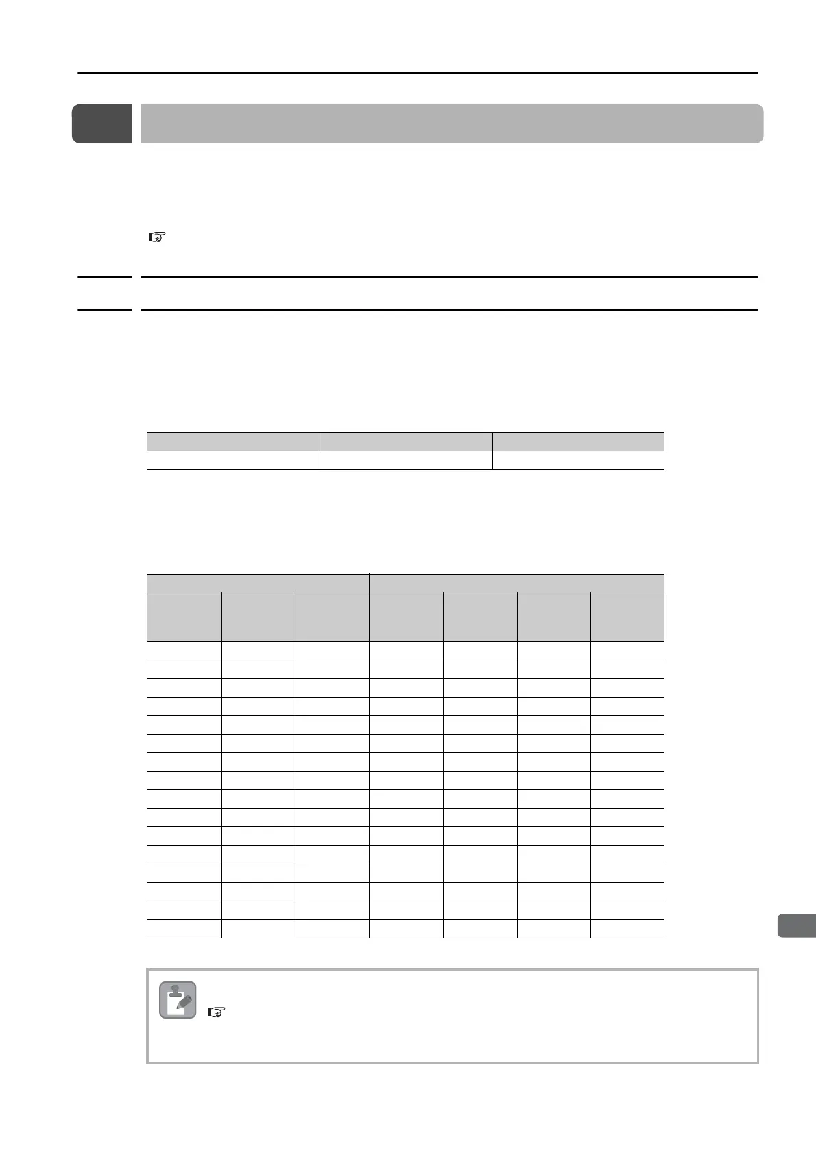
You can register the desired zones in the ZONE table. The ZONE table consists of settings for
the ZONE numbers (ZONE), ZONE N values (ZONE N), and ZONE P values (ZONE P). You can
register up to 16 zones.
The ZONE numbers identify the registered zones.
ZONE N is the lower limit of the ZONE and ZONE P is the upper limit of the ZONE. The setting
conditions for ZONE N and ZONE P are given in the following table.
The ZONE signals indicate the ZONE number. If the current value is within a zone registered in
the ZONE table, the corresponding ZONE number is output on the ZONE signals.
You can use the ZONE numbers as required, e.g., to trigger operations related to positioning
operations.
Note: 1: Signal is ON (active), 0: Signal is OFF (inactive).
Setting Range Setting Unit Default Setting
-99,999,999 to 99,999,999 Reference units 0
ZONE Table ZONE Signals
ZONE
Number
(ID)
ZONE N
[Reference
Units]
ZONE P
[Reference
Units]
/ZONE3 /ZONE2 /ZONE1 /ZONE0
0 ±nnnnnnnn ±pppppppp 0 0 0 0
1 ±nnnnnnnn ±pppppppp 0 0 0 1
2 ±nnnnnnnn ±pppppppp 0 0 1 0
3 ±nnnnnnnn ±pppppppp 0 0 1 1
4 ±nnnnnnnn ±pppppppp 0 1 0 0
5 ±nnnnnnnn ±pppppppp 0 1 0 1
6 ±nnnnnnnn ±pppppppp 0 1 1 0
7 ±nnnnnnnn ±pppppppp 0 1 1 1
8 ±nnnnnnnn ±pppppppp 1 0 0 0
9 ±nnnnnnnn ±pppppppp 1 0 0 1
10 ±nnnnnnnn ±pppppppp 1 0 1 0
11 ±nnnnnnnn ±pppppppp 1 0 1 1
12 ±nnnnnnnn ±pppppppp 1 1 0 0
13 ±nnnnnnnn ±pppppppp 1 1 0 1
14 ±nnnnnnnn ±pppppppp 1 1 1 0
15 ±nnnnnnnn ±pppppppp 1 1 1 1
Always save the ZONE table to flash memory after you edit it. Refer to the following section for
the procedure.
Saving the Program Table to Flash Memory in the SERVOPACK on page 7-31
If you turn OFF the power supply before you save changes to flash memory, the changes to the
ZONE table will be lost.
 Loading...


