diagrams for details.
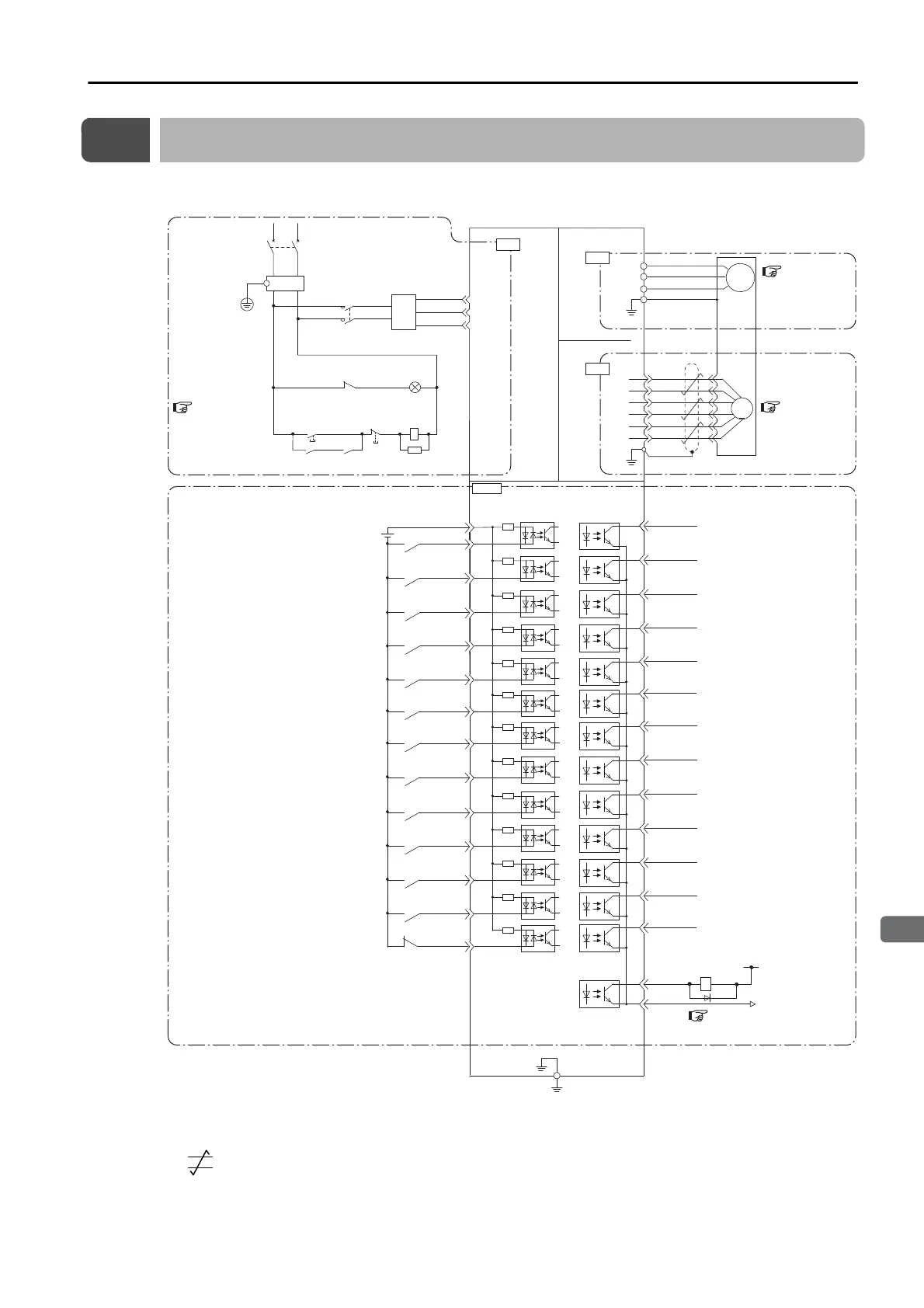
*1. represents twisted-pair wires.
*2. The 24-VDC power supply is not provided by Yaskawa. Use a 24-VDC power supply with double insulation or
reinforced insulation.
*3. The FG uses the mounting holes on the SERVOPACK.
ALM
COM_SG
19
18
20
21
22
23
24
25
26
27
28
29
30
31
17
+24 V
+24VIN
SI1 (/MODE)
SO1
(/INPOSITION)
General-purpose sequence output 1
(Positioning Completion Output)
SO2
(/POUT0)
SO3
(/POUT1)
SO4
(/POUT2)
SO5
(/POUT3)
SO6
(/POUT4)
SO7
(/POUT5)
SO8
(/PCO)
SO9
(/BUSY)
SO10
(/POSRDY)
SO11
(/PAREA)
SO12
(/S-ONS)
SO13
(E-STPS)
General-purpose sequence output 2
(Program Step Number Output 0)
General-purpose sequence output 3
(Program Step Number Output 1)
General-purpose sequence output 4
(Program Step Number Output 2)
General-purpose sequence output 5
(Program Step Number Output 3)
General-purpose sequence output 6
(Program Step Number Output 4)
General-purpose sequence output 7
(Program Step Number Output 5)
General-purpose sequence output 8
(Encoder Origin Output)
General-purpose sequence output 9
(Busy Output)
General-purpose sequence output 10
(Homing Completed Output)
General-purpose sequence output 11
(Program-Specied Area Output)
General-purpose sequence output 12
(SERVO ON Status Output)
General-purpose sequence output 13
(Emergency Stop Status Output)
SI2
(/START)
SI3
(/STOP)
SI4
(/HOME)
SI5 (/PGMRES,
/ALM-RST)
SI13
(E-STP)
7
4
6
5
8
9
SI6
(/JOGP, /SEL0)
16
3
General-purpose sequence input 1
(Mode Switch Input)
Sequence input
signal power supply input
General-purpose sequence input 4
(Homing Input)
General-purpose sequence input 3
(Program Table Operation Stop Input)
General-purpose sequence input 5
(Program Table Operation Reset Input and Alarm Reset Input)
General-purpose sequence input 13
(Emergency Stop Input)
General-purpose sequence input 6
(Forward Jog input or Program Step Selection Input 0)
General-purpose sequence input 2
(Program Table Operation Start Input)
Servo Alarm
output
Ground to a resistance of 100 Ω or less.
*2
*1
CN1
10
SI7
(/JOGN, /SEL1)
General-purpose sequence input 7
(Reverse Jog input or Program Step Selection Input 1)
11
SI8
(/SEL2)
General-purpose sequence input 8
(Program Step Selection Input 2)
12
SI9
(/SEL3)
General-purpose sequence input 9
(Program Step Selection Input 3)
13
SI10
(/SEL4)
General-purpose sequence input 10
(Program Step Selection Input 4)
14
SI11
(/SEL5)
General-purpose sequence input 11
(Program Step Selection Input 5)
15
SI12
(/S-ON)
General-purpose sequence input 12
(SERVO ON Input)
1QF: Molded-case circuit breaker
1FLT: Noise Filter
1KM: Magnetic Contactor
1Ry: Relay
1PL: Indicator lamp
1SA: Surge Absorber
1D: Flywheel diode
2
6
1
5
ENC
3
7
Phase A+
0 V
1Ry
1D
+24 V
Phase A−
Phase B+
Phase B−
PG5V
PG0V
U
V
W
M
SERVOPACK
CN2
1
P
N
FG
FG (frame ground)
*3
1KM
Insulated
AC/DC converter for
main circuit power supply
2
1QF
R
T
(For servo alarm
display)
1Ry
1PL
1KM
1SA
Power
supply
ON
Power
supply
OFF
1KM 1Ry
1FLT
3
CN3
CN4
 Loading...


