2.4 Selecting the Servomotor Capacity
2.4.1 Example of Capacity Selection for Servomotors
2-12
2.4
Selecting the Servomotor Capacity
When you select a Servomotor capacity, refer to the following selection example procedure.
2.4.1
Example of Capacity Selection for Servomotors
1.
Machine Specifications
2.
Speed Diagram
3.
Motor speed
4.
Load Torque
5.
Load Moment of Inertia
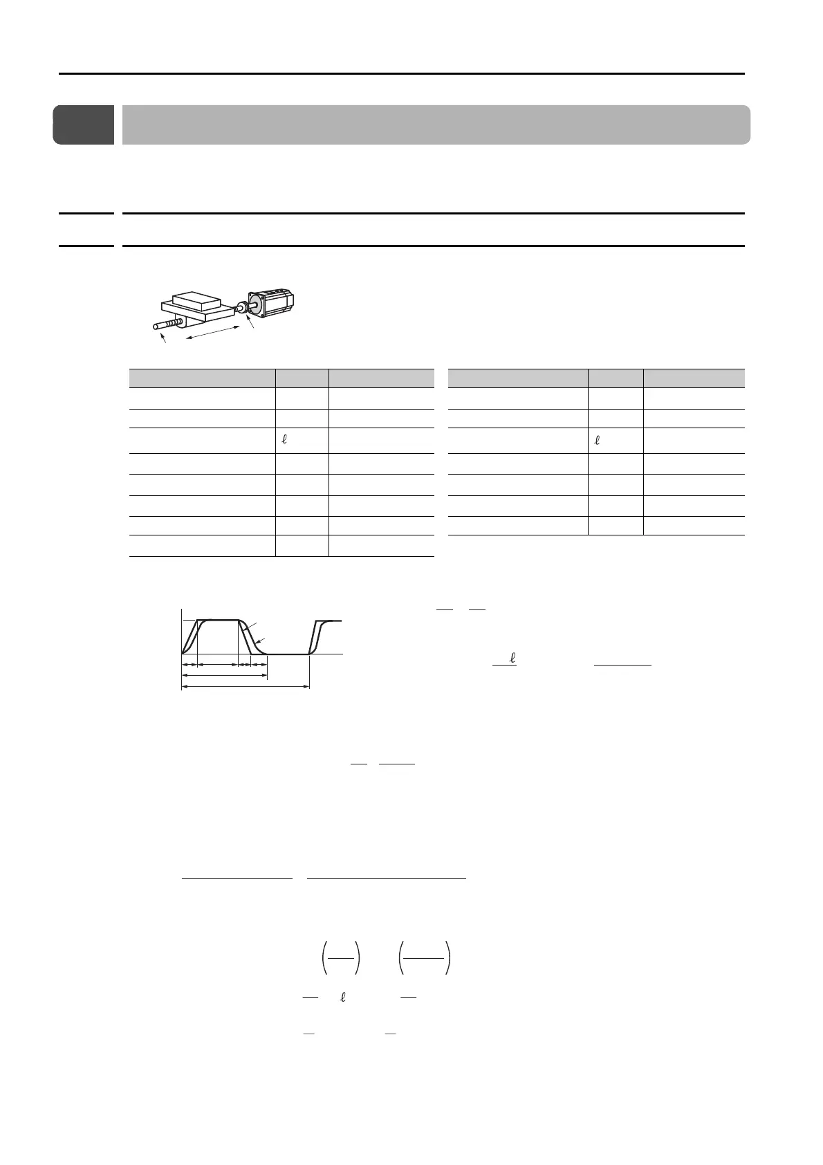
Item Symbol Value Item Symbol Value
Load Speed
υ
L
15 m/min
Coupling Outer Diameter
d
C
0.03 m
Linear Motion Section Mass
m 20 kg
Number of Feeding Operations
n 40 rotations/min
Ball Screw Length
B
0.3 m Feeding Distance 0.25 m
Ball Screw Diameter
d
B
0.008 m Feeding Time tm 1.2 s max.
Ball Screw Lead
P
B
0.005 m
Electrical Stopping Precision
δ
±0.02 mm
Ball Screw Material Density
ρ
7.87 × 10
3
kg/m
3
Friction Coefficient
μ
0.2
External Force on Linear Motion Section
F 0 N Mechanical Efficiency
η
0.9 (90%)
Coupling Mass
m
C
0.3 kg
• Load Shaft Speed
• Motor shaft speed Direct coupling gear ratio 1/R 1/R = 1/1
Therefore, n
M
= n
L
·R = 3,000 × 1 = 3,000 (min
-1
)
• Linear motion
section
• Ball screw
• Coupling
• Load moment of inertia at motor shaft
J
L
= J
L1
+ J
B
+ Jc = 0.474 × 10
-4
(kgm
2
)
Ball screw
Servomotor
Linear motion section
Coupling
υ
L
Load Speed
Reference Speed
Speed
(m/min)
Time (s)
tm
15
tcta td ts
t
υ
L
t = = = 1.5 (s)
if ta = td, ts = 0.1 (s),
ta = tm − ts − = 1.2 − 0.1 − = 0.1 (s)
tc = 1.2 − 0.1 − 0.1 × 2 = 0.9 (s)
60
n
60
40
60 × 0.25
15
60
υ
L
L
= = = 3000 (min
-1
)
P
B
15
0.005
υ
L
T
L
= = = 0.035 (N
m)
2πR ·
(9.8 · m + F ) · P
B
2π×1 × 0.9
(9.8 × 0.2 × 20 + 0) × 0.005
μ
η
J
L1
= m = 20 × = 0.127 × 10
-4
(kg
m
2
)
2
2πR
P
B
2
2π×1
0.005
B
= ·
B
· d
B
4
= × 7.87 × 10
3
× 0.3 × (0.008)
4
= 0.009 × 10
-4
(kg
m
2
)
32
π
32
π
ρ
c = m
C ·
d
C
2
= × 0.3 × (0.03)
2
= 0.338 × 10
-4
(kg
m
2
)
8
1
8
1
 Loading...


