2.5 Selecting Cables
2.5.6 I/O Signal Cables
2-18
2.5.6
I/O Signal Cables
Selection Table
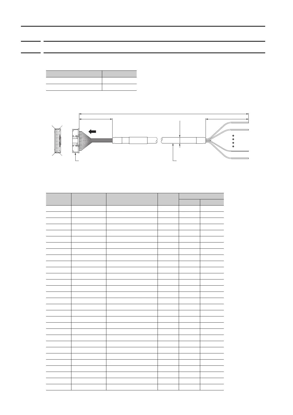
Dimensional Drawing
* The connector pin layout shown in the above figure is when the connector is viewed from the direction of the
arrow.
Wiring Specifications
Order Number Length (L)
JZSP-CSSI203-01P5-E 1.5 m
JZSP-CSSI203-03-E 3 m
Pin Signal Default Signals
Wire
Color
Markings
Color Number
1- - OrangeRed
2 FG - Orange Black
3 SI1 /MODE Gray Red
4SI2 /STARTGrayBlack
5SI3 /STOPWhiteRed
6SI4 /HOMEWhiteBlack
7 +24VIN - Yellow Red
8 SI5 /PGMRES, /ALM-RST Yellow Black
9 SI6 /JOGP, /SEL0 Pink Red
10 SI7 /JOGN, /SEL1 Pink Black
11 SI8 /SEL2 Orange Red
12 SI9 /SEL3 Orange Black
13 SI10 /SEL4 Gray Red
14 SI11 /SEL5 Gray Black
15 SI12 /S-ON White Red
16 SI13 E-STP White Black
17 COM_SG - Yellow Red
18 SO1 /INPOSITION Yellow Black
19 ALM - Pink Red
20 SO2 /POUT0 Pink Black
21 SO3 /POUT1 Orange Red
22 SO4 /POUT2 Orange Black
23 SO5 /POUT3 Gray Red
24 SO6 /POUT4 Gray Black
25 SO7 /POUT5 White Red
26 SO8 /PCO White Black
27 SO9 /BUSY Yellow Red
28 SO10 /POSRDY Yellow Black
29 SO11 /PAREA Pink Red
30 SO12 /S-ONS Pink Black
L
Connector: PUDP-32V-S (from J.S.T. Mfg. Co., Ltd.)
Contacts: SPUD-002T-P0.5 (from J.S.T. Mfg. Co., Ltd.)
SERVOPACK end Host controller end
Unit: mm
Cable (UL2464)
AWG28 × 32C
100
+10
2
32
31
1
0
(8.3 dia.)
100
+10
0
*
 Loading...


