4.4 Wiring Servomotors
4.4.2 Pin Arrangement of Servomotor Connector (CN4)
4-12
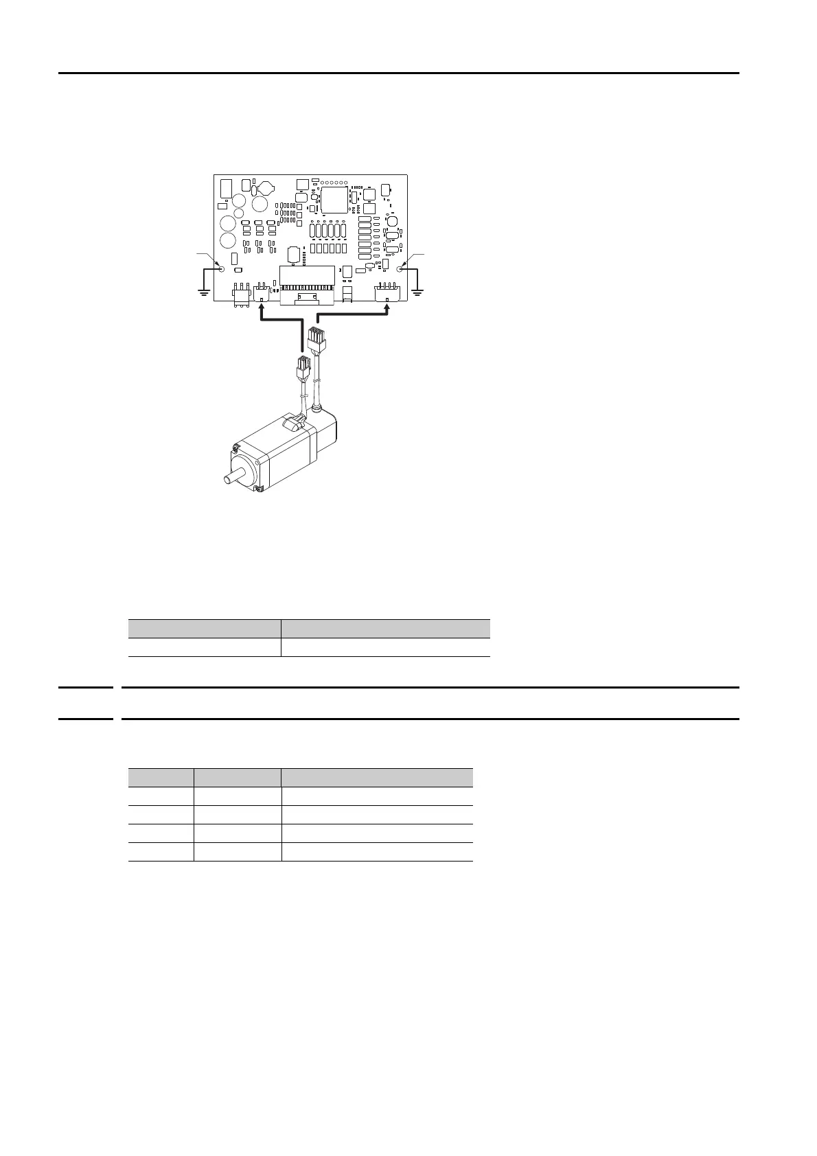
Grounding Precautions
Always use the mounting holes in the SERVOPACK to ground the PCB. The Servomotor is
grounded through the Servomotor Power Cable.
Cable Precautions
Do not use the cables given in 2.5.1 Cable Selection Table in applications that require a high
degree of flexibility, such as twisting and turning, or in which the cables themselves must move.
Observe the recommended bending radius given in the following table and perform wiring so
that stress is not applied to the cables. Use the cables so that they are not repeatedly bent.
4.4.2
Pin Arrangement of Servomotor Connector (CN4)
The connector pin layout that is required to connect the SERVOPACK to a Servomotor is given
below.
Cable Diameter Recommended Bending Radius [R]
Less than 8 mm dia. 15 mm min.
Servomotor
Mounting hole
Mounting hole
Pin Signal Function
1 U Servomotor phase-U terminal
2 V Servomotor phase-V terminal
3 W Servomotor phase-W terminal
4 FG Frame ground terminal
 Loading...


