8.8 Manual Tuning
8.8.1 Tuning the Servo Gains
8-33
Example Adjustment Procedure
Adjusted Servo Gains
You can set the following gains to adjust the response characteristic of the SERVOPACK.
• Pn100: Speed Loop Gain
• Pn101: Speed Loop Integral Time Constant
• Pn102: Position Loop Gain
• Pn401: First Stage First Torque Reference Filter Time Constant
Position Loop Gain
The position loop gain determines the response characteristic of the position loop in the SER-
VOPACK. If you can increase the setting of the position loop gain, the response characteristic
will improve and the positioning time will be shortened. However, you normally cannot increase
the position loop gain higher than the inherit vibration frequency of the machine system. There-
fore, to increase the setting of the position loop gain, you must increase the rigidity of the
machine to increase the inherit vibration frequency of the machine.
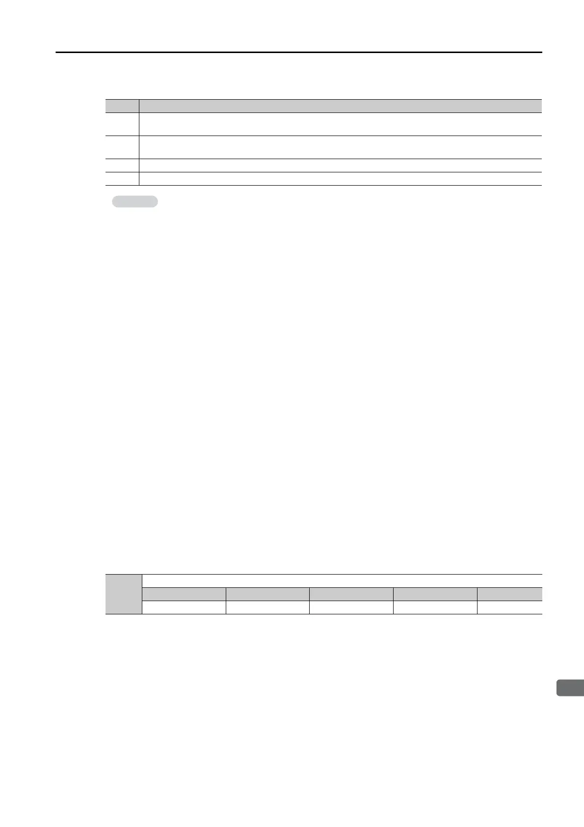
Step Description
1
Adjust the first stage first torque reference filter time constant (Pn401) so that vibration does not
occur.
2
Increase the position loop gain (Pn100) and reduce the speed loop integral time constant (Pn101) as
far as possible within the range that does not cause machine vibration.
3 Repeat steps 1 and 2 and return the settings about 10% to 20% from the values that you set.
4 Increase the position loop gain (Pn102) within the range that does not cause vibration.
If you greatly change any one servo gain parameter, you must adjust the other parameters
again. Do not increase the setting of just one parameter. As a guideline, adjust the settings of
the servo gains by approximately 5% each. As a rule, change the servo parameters in the fol-
lowing order.
• To Increase the Response Speed
1. Reduce the torque reference filter time constant.
2. Increase the speed loop gain.
3. Decrease the speed loop integral time constant.
4. Increase the position loop gain.
• To Reduce Response Speed and to Stop Vibration and Overshooting
1. Reduce the position loop gain.
2. Increase the speed loop integral time constant.
3. Decrease the speed loop gain.
4. Increase the torque filter time constant.
Pn102
Position Loop Gain
Setting Range Setting Unit Default Setting When Enabled Classification
10 to 20,000 0.1/s 400 Immediately Tuning
 Loading...


