4.3 Wiring the Power Supply to the SERVOPACK
4.3.3 Power Supply Wiring Diagrams
4-10
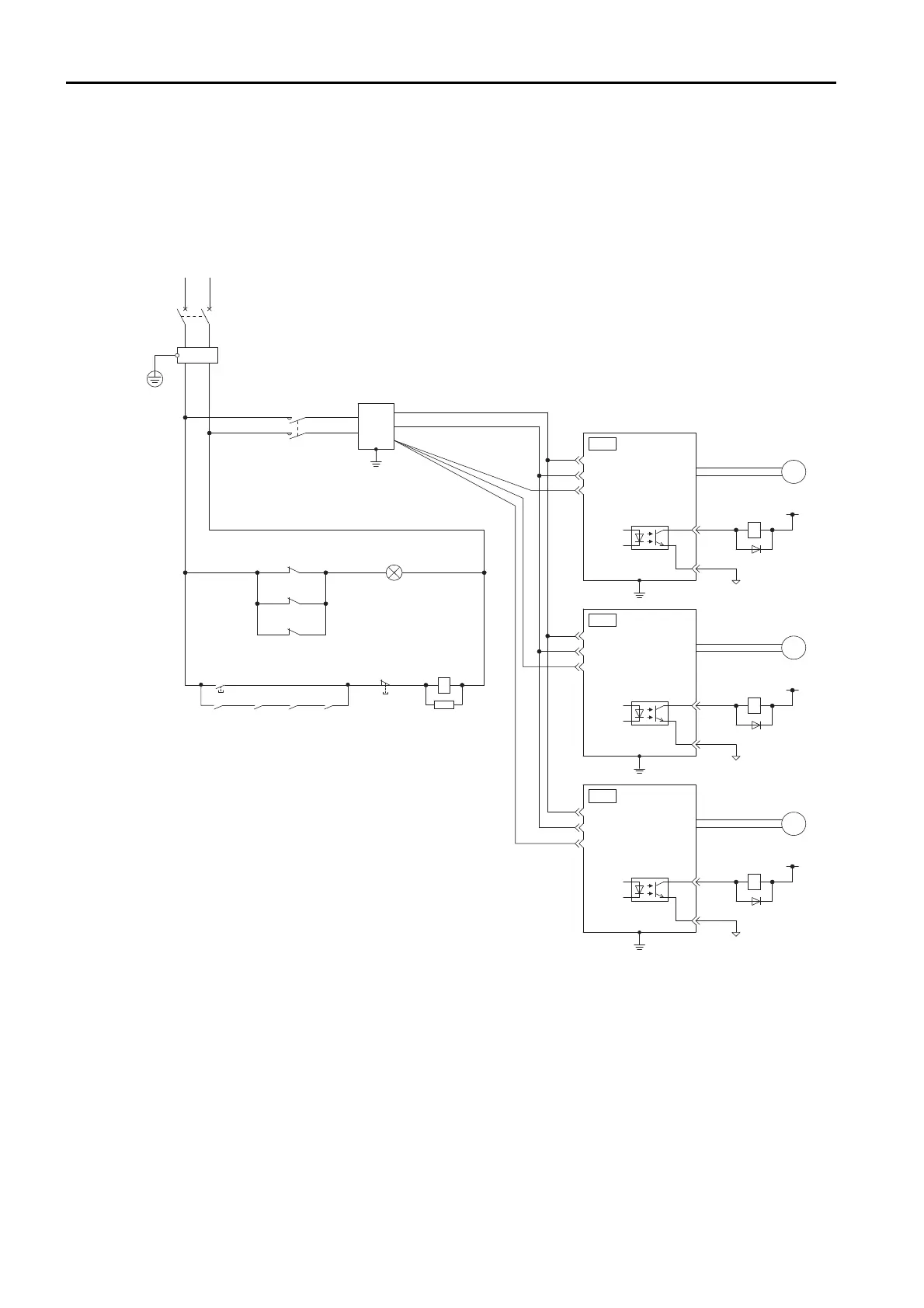
Using More Than One SERVOPACK
The following diagram shows the wiring to stop all of the Servomotors when there is an alarm
for any one SERVOPACK.
More than one SERVOPACK can share a single Noise Filter. However, always select a Noise Fil-
ter that has a large enough capacity to handle the total power supply capacity of all the
SERVOPACKs. Be sure to consider the load conditions.
Note: When you shut OFF the power supply with a magnetic contactor or other device, do so before the insulated
AC/DC converter for the power supply.
1QF: Molded-case circuit breaker
1FLT: Noise Filter
1KM: Magnetic Contactor
1Ry: Relay
2Ry: Relay
3Ry: Relay
1PL: Indicator lamp
1SA: Surge Absorber
1D: Flywheel diode
2D: Flywheel diode
3D: Flywheel diode
RT
1QF
1FLT
1KM
Insulated AC/DC converter
for main circuit power supply
(For servo alarm display)
1PL
1Ry
2Ry
3Ry
1KM
1SA
SERVOPACK
1
2
1
2
3
P
N
3
FG
P
N
FG
1
2
3
P
N
FG
COM
_
SG
ALM
1Ry
1D
0 V
+24 V
Servomotor
M
SERVOPACK
COM
_
SG
ALM
2Ry
2D
0 V
+24 V
Servomotor
M
SERVOPACK
COM
_
SG
ALM
3Ry
3D
0 V
+24 V
Servomotor
M
CN3
CN3
CN3
Power
supply
ON
Power
supply
OFF
1KM 1Ry 2Ry 3Ry
 Loading...


