4 Cabling the AC 800F
4-51
Transceiver Delay equivalent
10Base2/AUI transceiver (miniature) 50 m
10Base2/AUI transceiver (flush-mount) 50 m
10Base5/AUI transceiver 50 m
10BaseFL transceiver (miniature) 30 m
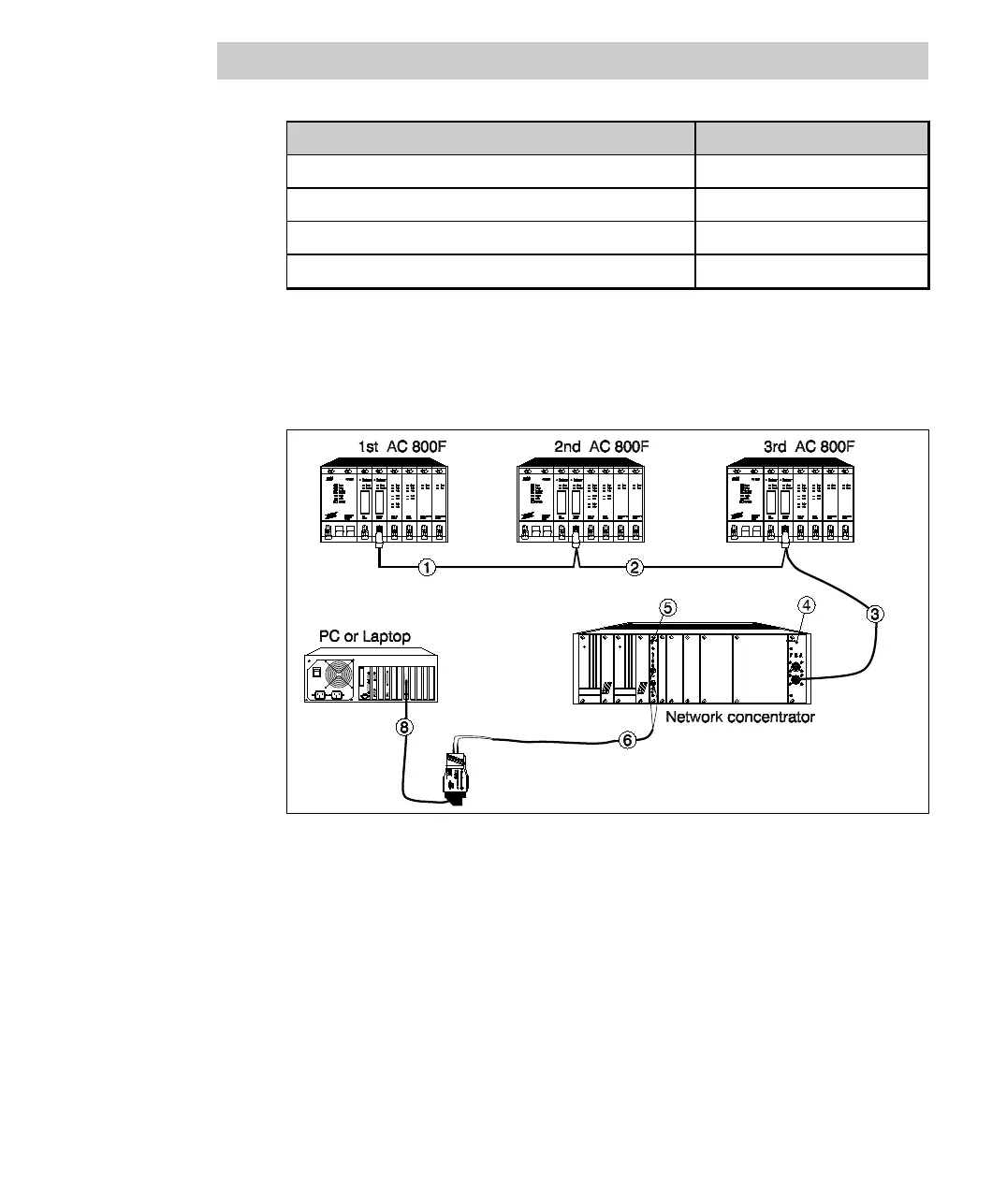
Example:
Figure 4-29 shows an example for an installation which illustrates the calculation of
the propagation delay.
Fig. 4-29 Propagation delay calculation for an installation, example
In Fig. 4-29 the longest signal path is from AC 800F 1 over AC 800F 2 to AC 800F 3,
via the 10Base5 concentrator module, the 10BaseFL concentrator module, the
10BaseFL cable, the 10BaseFL transceiver, and the AUI cable to the operator station.
The numbers 1 ... 8 marked with circles indicate the signal path and can also be found
in the table below. The cable lengths and propagation delay equivalents of the
electronic components on this path have to be added.