7 Functional Description of the Fieldbus Modules
7-28
7.4.2 Hardware structure
The following hardware components are used in the CAN module:
• CAN communication controller (HICAN) for each channel
• CAN driver for each channel
• High-speed optocouplers for electrical isolation of the communication signals
• Discrete DC/DC converter with two electrically isolated output voltages for the
communication channels
• Optocouplers for monitoring the electrically isolated voltages and, thus,
possibility of alarm signaling in case of failure
• EEPROM for configuration data
• Isolator allowing you to plug the module in or remove it while the AC 800F is
running.
• 9-pin Sub-D socket with the bus signals of the three CAN channels.
In order to ensure electromagnetic compatibility, the bus signals of the CAN channels
are applied to the Sub-D socket via SMD-EMC filters.
Data is transferred between the AC 800F and the CAN module via a 16-bit data bus.
The transmit and receive data is exchanged with the CPU through interrupt control.
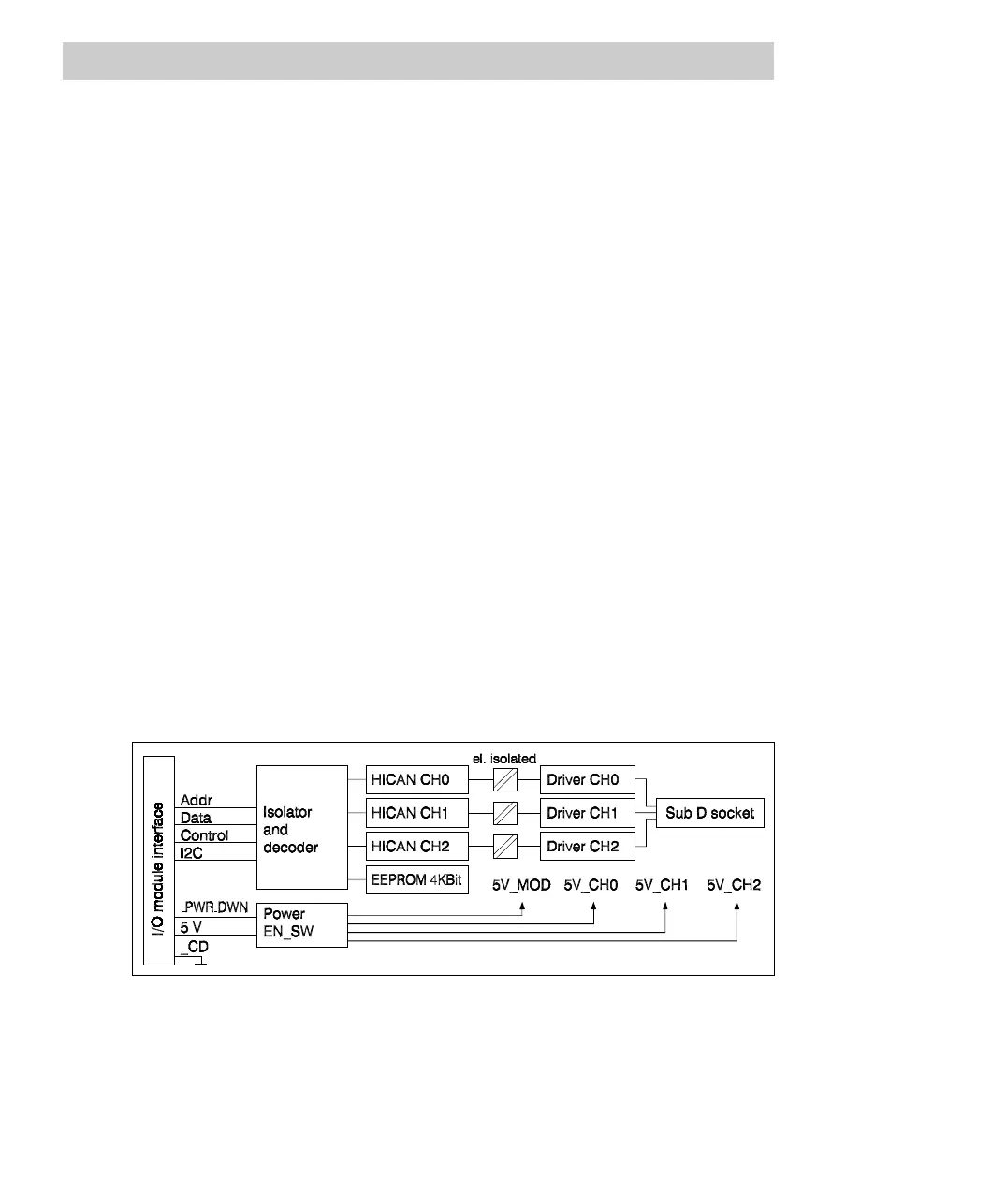
Block diagram
Fig. 7-12 FI 810F block diagram