6 Functional Description of the Ethernet Modules
6-39
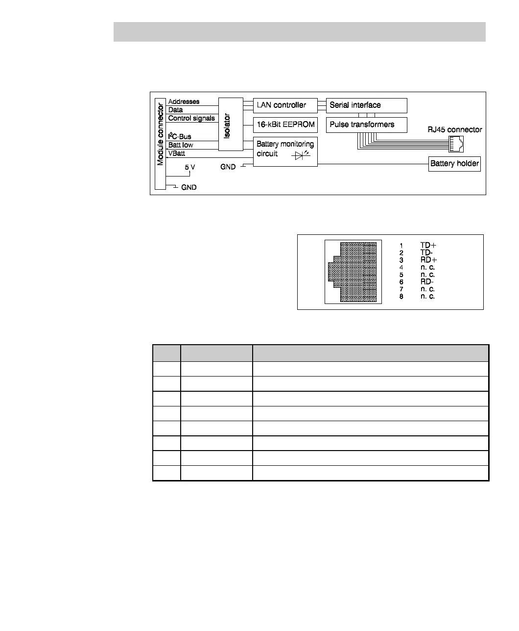
Block diagram
Fig. 6-18 10BaseT module block diagram
Connector pin assignment
RJ45 socket
Fig. 6-19 10BaseT module connector pin assignment
Pin: Signal Description
1 TD+ Transmit signal +
2 TD- Transmit signal -
3 RD+ Receive signal +
4 n. c. Not used
5 n. c. Not used
6 RD- Receive signal -
7 n. c. Not used
8 n. c. Not used
Two different cable types are available for connecting a 10BaseT module:
• Use a cable with the transmit branch (TD+/TD-) of one module crossed over the
receive branch (RD+/RD-) of the other module (cross cable) for a redundancy link
between two 10BaseT modules or for a direct link between two 10BaseT nodes.
• When connecting other components, e.g. a hub, this cross-over is done in the
connector. As a result, a 1:1 cable has to be used.