4 Cabling the AC 800F
4-61
Preparing a Profibus cable
• Cut the Profibus cable type A to the required lengths. Strip off the insulation from
the cable ends.
• Observe the manufacturer instructions for the Profibus connector.
• Make sure not to confound feed and return wires. The incoming and outgoing
signals must not be applied to the same pin.
• Connect the bare (non-insulated) wire ends to the appropriate pins. It is
recommended to note down the wire color to avoid that the data lines will be
confounded when the network will be extended at a later time.
• Make sure that the braid shield and, if applicable, the tape shield underneath it, is
in good contact with the appropriate connector pin.
• Use an ohmmeter to check the static characteristics of the ready made cable:
Passage on pin 3 between all Profibus connectors.
Passage on pin 8 between all Profibus connectors.
Insulation between pin 3 and pin 8 with bus termination switched off.
one bus termination switched on ➩ around 390 ohms between pin 3 and 6
both bus terminations switched on ➩ around 195 ohms between pin 3 and 6
one bus termination switched on ➩ around 220 ohms between pin 3 and 8.
both bus terminations switched on ➩ around 110 ohms between pin 3 and 8
one bus termination switched on ➩ around 390 ohms between pin 8 and 5
both bus terminations switched on ➩ around 195 ohms between pin 8 and 5
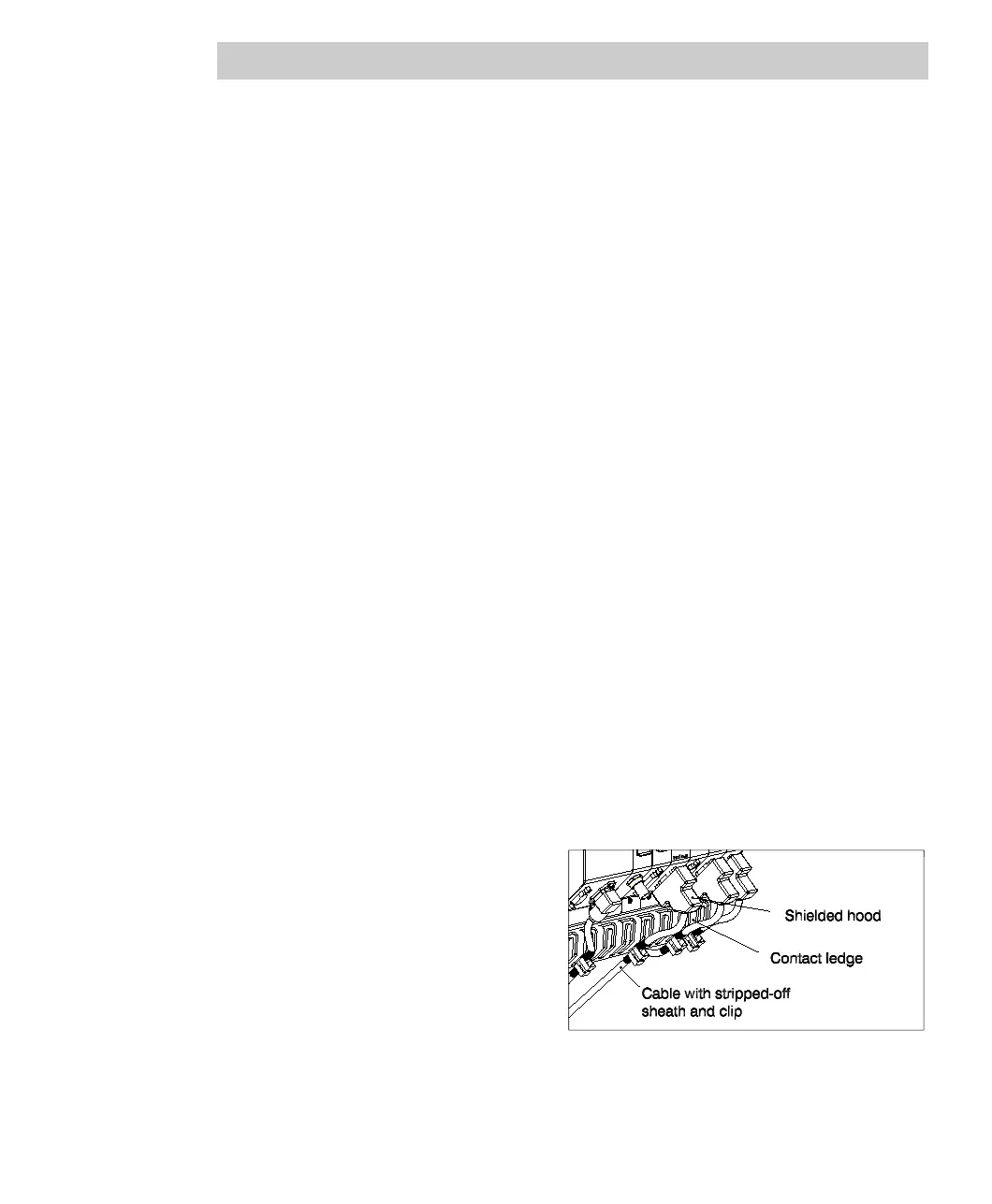
• Switch on the bus termination
of the end connectors (no
outgoing lines).
• Put the shield of the Profibus
cable on the contact ledge
and fasten with a clip
TV 83xF.
• Put on the shield for every
node of a line and make sure
there is a good contact.
Fig. 4-38 Grounding FI 830F